写在前面
关于本书 / About This Book
本书基于 ImplFerris/pico-pico 原项目改编,在原作 Rust 嵌入式内容的基础上,新增了 C (Pico SDK) 实现作为对照。采用「同一个概念,C 和 Rust 两种写法」的编排方式,帮助读者在嵌入式学习中同时掌握两门语言。
如果你在阅读过程中发现任何问题,欢迎通过以下方式反馈:

为什么 C + Rust 双轨?
嵌入式开发的两个世界:
- C + Pico SDK — 离硬件最近,寄存器级别的控制,让你理解 MCU 真正在做什么
- Rust + Embassy — 现代异步框架,类型安全,编译期就能消灭一大类 bug
同一块 Pico 2,同一个外设,两种写法并排对照,比单独学任何一门都更高效。
阅读建议
- 如果你有 C 基础但没接触过 Rust → 先看 C 实现理解硬件,再对比 Rust 的抽象写法
- 如果你熟悉 Rust 但不熟嵌入式 → 先看 Rust 实现快速上手,再翻 C 实现理解底层
- 如果你两门都刚入门 → 按章节顺序走,每个外设的原理只看一遍,代码两边都读
🌟 原项目仓库 / Original Repository

点击上方按钮前往原项目仓库,为原作者 ImplFerris 点个 Star!
Please visit the original repository and give it a star!
impl Rust & C for RP2350 - 简介
本书基于 ImplFerris/pico-pico 原项目改编,在原作 Rust 嵌入式内容的基础上,新增了 C (Pico SDK) 实现作为对照。采用「同一个概念,C 和 Rust 两种写法」的编排方式,帮助自己在嵌入式学习中同时掌握两门语言。
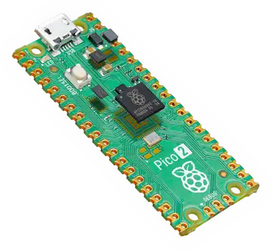
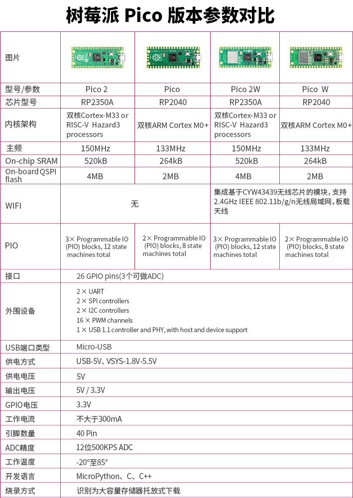
硬件介绍 - Pico 2 & Pico 2 W
本书使用基于新型 RP2350 芯片的 Raspberry Pi Pico 2 和 Raspberry Pi Pico 2 W。它们提供双核灵活性,支持 ARM Cortex-M33 核心,并可选 Hazard3 RISC-V 核心。默认情况下,它们使用标准的 ARM 核心运行,但开发者如需要也可选择尝试 RISC-V 架构。
可以访问官方网站获取更多内容:Pico 2
Note
源项目 https://github.com/ImplFerris/pico-pico 主要基于 Pico 2。本项目在此基础上继续扩展,示例同时支持 Pico 2 和 Pico 2 W。
Pico 2 W 支持 Wi-Fi 和蓝牙功能,同样基于 RP2350 芯片。对于普通 GPIO、PWM、ADC、I2C、SPI 等外设章节,Pico 2 和 Pico 2 W 的核心用法保持一致;涉及板载 LED、无线芯片或引脚差异的章节,会在内容中给出对应说明。
开发工具对照
本书的 C 和 Rust 示例各自使用对应的烧录和调试工具:
| 用途 | C 工具 | Rust 工具 |
|---|---|---|
| BOOTSEL 模式烧录(无 Debug Probe) | picotool | picotool |
| Debug Probe 烧录与调试 | openocd | probe-rs |
如果没有 Debug Probe,配置 picotool 就足够完成大多数入门示例。具体安装步骤见 C SDK 环境 和 Rust 环境。
数据手册
如需查看详细的技术信息、规格参数和设计指南,可以参考官方数据手册:
许可证
《C-PICO-RUST-BOOK》(本项目)采用以下许可证发布:
- 本书中的代码示例和独立 Cargo 项目同时采用 MIT License 和 Apache License v2.0 授权。
- 本书中的文字内容采用 Creative Commons CC-BY-SA v4.0 许可证授权。
- 本书中的电路图使用 Fritzing 绘制。
所需硬件
要跟随本书完成所有示例,除了 Pico 2 / Pico 2 W 开发板本身外,还需要一些基础硬件。
元件清单 列出了书中所有用到的电子元件,每个涉及的硬件都匹配了对应使用的章节,可以不同一次买齐,可以按需逐步添置。
特别重要的硬件我会单独列出来,作为一个章节,比如:调试探针
元件清单
Important
某些组件可能需要焊接操作,例如将排针焊接到显示屏或传感器模块等电路板上。许多部件也提供已预先焊接好的版本。
如果某个组件没有附带引脚,则使用前必须先进行焊接。焊接是嵌入式工作中的一项实用技能,请耐心操作并遵守基本的安全措施。
以下列出的是参考用的器件名称,在购买之前请查阅对应的章节内容以确认所选模块类型及其引脚布局是否与书中的实例一致:
| 组件 | 所用的数量 | 章节 |
|---|---|---|
| 杜邦线(公对公 / 公对母) | 若干 | ALL |
| [官方Debug-Probe,带JST-SH 3pin 转 2.54mm、三针 JST-SH 连接器] (可选硬件) | 1 | ALL |
Raspberry Pi Pico 2 的调试探针
Raspberry Pi Debug Probe 是官方推荐用于 Pico 和 Pico 2 上 SWD 调试的工具。它是一个小型 USB 设备,充当 CMSIS-DAP 适配器。CMSIS-DAP 是一种开放的调试器标准,它让你的电脑可以通过 SWD 协议与微控制器通信。
这个探针提供两个主要功能:
-
SWD(Serial Wire Debug)接口 - 它连接到 Pico 的调试引脚,用于烧录固件和进行实时调试。你可以像在普通桌面应用里一样设置断点、查看变量并调试程序。
-
UART 桥接 - 它提供 USB 转串口连接,让你可以查看控制台输出或与开发板通信。
这两个功能都通过连接到电脑的同一根 USB 线工作,因此安装起来很简单,因为你不需要额外的 UART 设备。
焊接 SWD 引脚
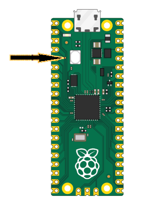
在把 Debug Probe 连接到 Pico 2 之前,你需要先让 SWD 引脚可用。这些引脚位于 Pico 板子的底边,在一个与主 GPIO 引脚分开的 3 针调试排针上。
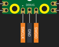
SWD 引脚焊好之后,你的 Pico 就可以连接到 Debug Probe 了。
准备 Debug Probe
你的 Debug Probe 可能不会预装最新固件,尤其是支持 Pico 2(RP2350 芯片)的版本。建议你在开始前先更新固件。
Raspberry Pi 官方文档提供了更新 Debug Probe 的清晰说明。请按照这里的步骤操作。
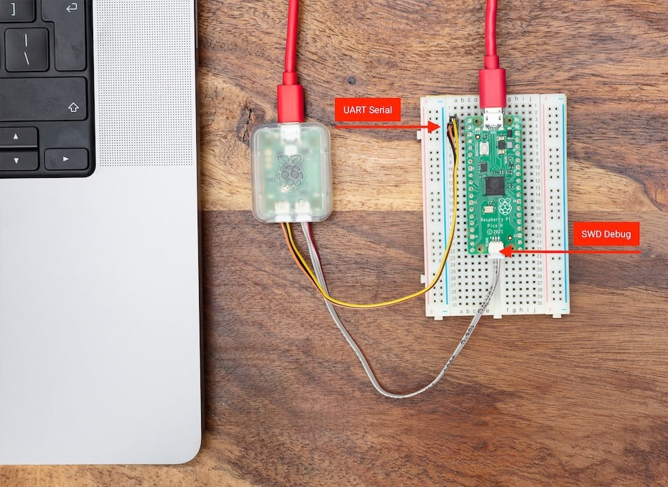
将 Pico 与 Debug Probe 连接起来
Debug Probe 侧面有两个接口:
- D 端口 - 用于 SWD(调试)连接
- U 端口 - 用于 UART(串口)连接
SWD 连接(必需)
SWD 连接负责让你烧录固件并使用调试器。请使用 Debug Probe 随附的 JST 转杜邦线。
将 Debug Probe D 端口上的导线按下面方式连接到 Pico 2 引脚:
| Probe Wire | Pico 2 Pin |
|---|---|
| Orange | SWCLK |
| Black | GND |
| Yellow | SWDIO |
在连接之前,请确认 Pico 2 的 SWD 引脚已经正确焊好。
UART 连接(可选)
如果你想在电脑终端里看到串口输出,UART 连接就很有用。它与 SWD 连接是分开的。
将 Debug Probe U 端口上的导线连接到 Pico 2 引脚:
| Probe Wire | Pico 2 Pin | Physical Pin Number |
|---|---|---|
| Yellow | GP0 (TX on Pico) | Pin 1 |
| Orange | GP1 (RX on Pico) | Pin 2 |
| Black | GND | Pin 3 |
你也可以使用任何配置为 UART 的 GPIO 引脚,但 GP0 和 GP1 是 Pico 的默认 UART0 引脚。
给 Pico 供电
Debug Probe 不会给 Pico 2 供电,它只提供 SWD 和 UART 信号。要给 Pico 2 供电,请先通过 Debug Probe 的 USB 口把它连接到电脑,再通过 Pico 2 自己的 USB 连接单独供电。调试正常工作时,这两个设备都必须通电。
最终设置
连接完成后:
- 将 Debug Probe 通过 USB 插到电脑上
- 确保你的 Pico 2 已经通电
- Debug Probe 的红色 LED 应该亮起,表示它已经供电
- 你的环境已经准备好 - 从现在开始不需要再按 BOOTSEL 按钮了
现在你可以直接通过开发环境给 Pico 2 烧录和调试,不需要任何手动介入。
自己做一块?
本质上官方这个调试探针其实就是另一块 Pico 板子,如果你有另一块pico板子,也可以自己刷入调试固件,可以参考链接:
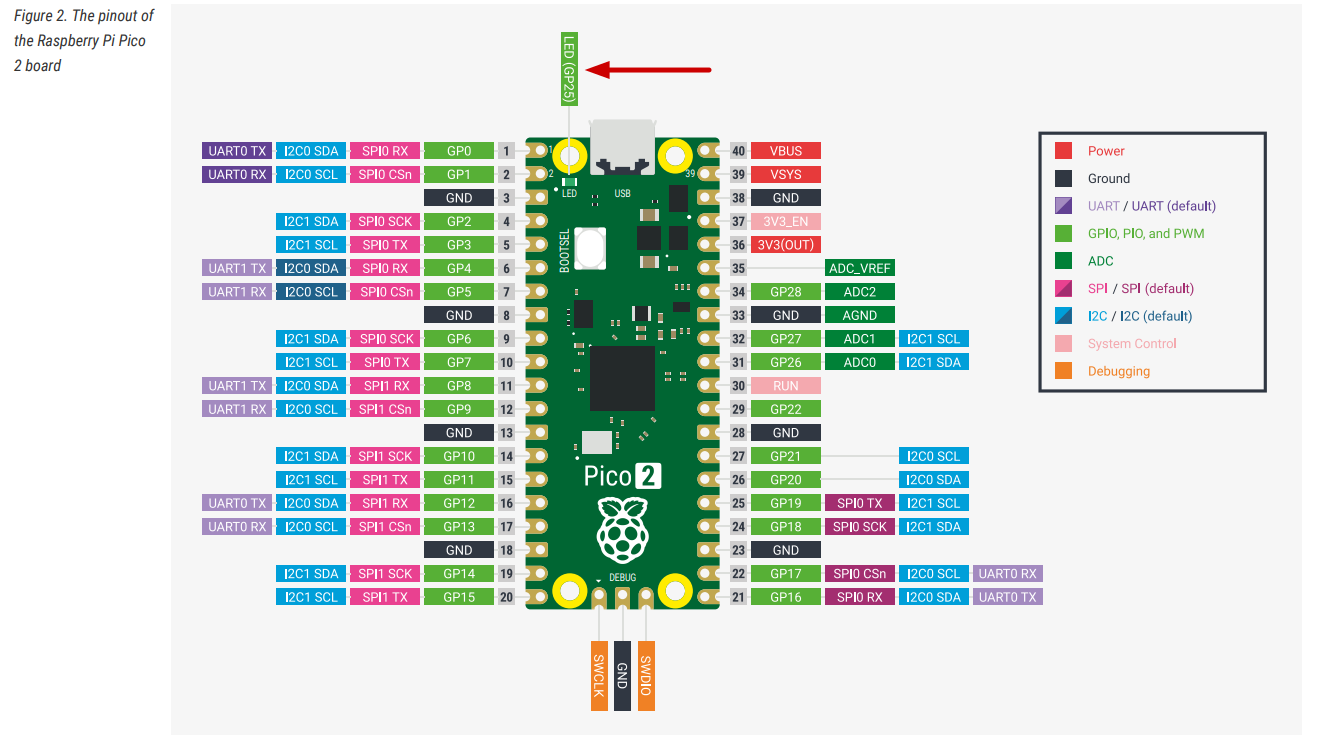
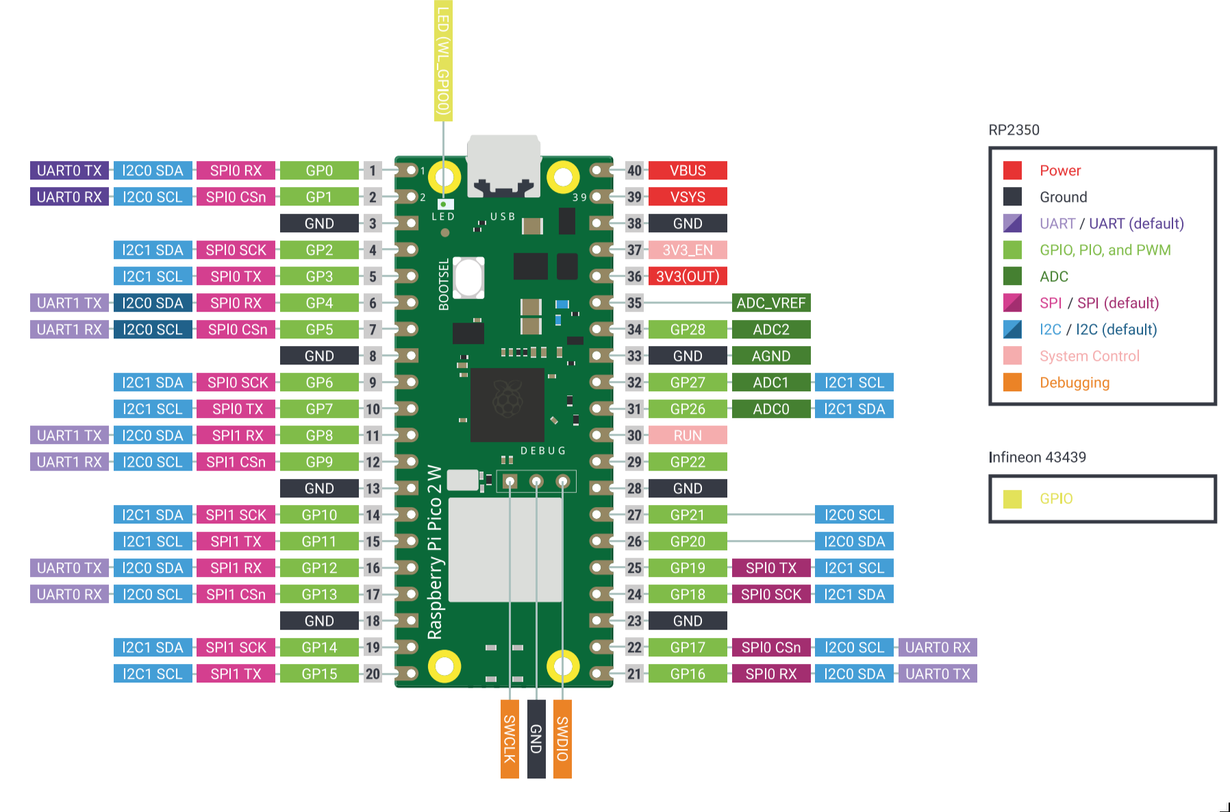
引脚图
Tip
你现在不需要记住或理解每一个引脚。用到的时候随时回顾即可
“树莓派 Pico 2 引脚图”
“树莓派 Pico 2 W 引脚图”
电源引脚
Raspberry Pi Pico 2 / Pico 2 W 具有以下电源引脚。 引脚在引脚图中以红色(电源)和黑色(地线)标出,用于为主板及外部组件供电。
-
VBUS 连接到来自 USB 端口的 5 V 电压。当主板通过 USB 供电时,该引脚将提供约 5 V 的电压。您可以使用它来驱动小型外部电路,但不适合高电流负载。
-
VSYS 是主板的主要电源输入端口。您可以在该端口连接电池或稳压电源,输入电压范围为 1.8 V 至 5.5 V。此引脚为主板上的一个3.3V稳压器供电,进而为 RP2350 芯片及其他部件提供电力。
-
3V3(OUT) 提供来自板载稳压器的稳定输出电压:3.3 V。可用于给外部设备如传感器或显示屏等元件供电,但建议限制电流不超过 300 mA。
-
GND 引脚用于完成电气回路,并与系统接地相连。Pico 2 / Pico 2 W 在整个开发板上分布多个 GND 引脚,方便连接外部设备。
GPIO引脚
Raspberry Pi Pico 2 和 Pico 2 W 的主排针都引出了 26 个 RP2350 通用输入/输出(GPIO)引脚:GPIO0 到 GPIO22,以及 GPIO26 到 GPIO28。GPIO23、GPIO24、GPIO25 和 GPIO29 没有作为普通排针 GPIO 引出,而是用于板载功能;其中 Pico 2 和 Pico 2 W 的具体用途不同,见上面的差异表。
这些 GPIO 引脚非常灵活,可用于读取开关或传感器等输入信号,也可用于控制 LED、电机或其他设备等输出。所有排针 GPIO 均以 3.3 V 的逻辑电平工作。这意味着你连接的任何输入信号电压都不应超过 3.3 V,否则可能损坏电路板。除了基本的数字输入/输出功能,部分引脚还支持模拟输入(ADC),或者作为 I²C、SPI、UART 等协议的通信线路使用。
引脚编号
每个 GPIO 引脚都可以通过两种方式来引用:
- 一种是使用其 GPIO 编号(在软件中使用);
- 另一种是使用其在电路板上的物理引脚位置。
在编写代码时,你需要使用 GPIO 编号(例如 GPIO0);而在连接导线时,则需要知道哪个 GPIO 引脚对应于电路板上的哪个物理引脚。
ADC 引脚
Pico 2 / Pico 2 W 上的大多数 GPIO 都是数字引脚,只能读取或输出高电平、低电平这样的离散状态。但有些设备,比如光敏传感器、温度传感器,会输出逐渐变化的电压。为了读取这种模拟信号,我们需要使用一种特殊的引脚:ADC 引脚。
ADC 是 Analog-to-Digital Converter 的缩写,意思是“模数转换器”。它会把输入电压转换成程序可以理解的数字。例如,0 V 可能会被转换成 0,而 3.3 V 可能会被转换成 4095(因为 ADC 使用 12 位分辨率,4095 是它能表示的最大值)。
Raspberry Pi Pico 2 / Pico 2 W 的排针上都有三个可以作为 ADC 使用的引脚:GPIO26、GPIO27 和 GPIO28。它们分别对应 ADC0、ADC1 和 ADC2。你可以用这些引脚读取光敏传感器、温度传感器等设备输出的模拟信号。
另外,RP2350 还有一个 ADC3 通道。在 Pico 2 上,GPIO29/ADC3 用来测量 VSYS/3;在 Pico 2 W 上,GPIO29/ADC3 还与无线芯片的 SPI clock 复用,所以读取 VSYS 时要避开无线 SPI 正在通信的时刻。这个引脚不是普通排针 ADC 引脚,初学时通常先使用 GPIO26、GPIO27、GPIO28。
还有两个和模拟读取有关的特殊引脚:
-
ADC_VREF 是 ADC 的参考电压。默认情况下,它连接到 3.3 V,这意味着 ADC 会把 0 V 到 3.3 V 之间的输入电压转换成数字。如果你希望在更小的电压范围内获得更高精度,也可以给这个引脚提供不同的参考电压,例如 1.25 V。
-
AGND 是模拟地,用于给模拟信号提供更干净的地参考。这样可以减少噪声,让模拟读取结果更稳定。如果你正在连接模拟传感器,通常建议把传感器的 GND 接到 AGND,而不是普通的 GND 引脚。
I2C 引脚
Raspberry Pi Pico 2 / Pico 2 W 支持 I2C。I2C 是一种常见的通信协议,只需要两根信号线就可以连接多个设备,常用于传感器、显示屏和其他外设。
I2C 使用两个信号:SDA(数据线)和 SCL(时钟线)。所有连接到同一条 I2C 总线上的设备都会共享这两根线。每个设备都有自己的地址,所以 Pico 2 / Pico 2 W 可以通过同一组 SDA/SCL 与多个设备通信。
Raspberry Pi Pico 2 / Pico 2 W 有两个 I2C 控制器:I2C0 和 I2C1。每个控制器都可以映射到多组 GPIO 引脚上,因此你可以根据电路布局灵活选择合适的引脚组合。
-
I2C0 可以使用以下 GPIO:
- SDA(数据):GPIO0、GPIO4、GPIO8、GPIO12、GPIO16 或 GPIO20
- SCL(时钟):GPIO1、GPIO5、GPIO9、GPIO13、GPIO17 或 GPIO21
-
I2C1 可以使用以下 GPIO:
- SDA(数据):GPIO2、GPIO6、GPIO10、GPIO14、GPIO18 或 GPIO26
- SCL(时钟):GPIO3、GPIO7、GPIO11、GPIO15、GPIO19 或 GPIO27
你可以从同一个控制器中选择一组匹配的 SDA 和 SCL 引脚。例如,如果选择 I2C0,就应该从 I2C0 的 SDA/SCL 列表中各选一个对应组合。
SPI 引脚
SPI(Serial Peripheral Interface,串行外设接口)也是一种常见的通信协议,常用于连接显示屏、SD 卡、传感器等设备。和 I2C 相比,SPI 需要更多信号线,但通常可以提供更高的通信速度。SPI 通常由一个控制器(例如 Pico 2 / Pico 2 W)连接一个或多个外设。
SPI 使用四个主要信号:
- SCK(Serial Clock):串行时钟,用于控制数据传输的时序。
- MOSI(Master Out Slave In):控制器发送给外设的数据线。
- MISO(Master In Slave Out):外设发送给控制器的数据线。
- CS/SS(Chip Select / Slave Select):片选信号,用于选择当前要通信的外设。
在 Pico 2 / Pico 2 W 的引脚图中,MOSI 通常标为 Tx,MISO 标为 Rx,CS 标为 Csn。
Raspberry Pi Pico 2 / Pico 2 W 有两个 SPI 控制器:SPI0 和 SPI1。每个控制器都可以连接到多组 GPIO 引脚,因此你可以根据电路布局选择合适的一组。
-
SPI0 可以使用:
- SCK:GPIO2、GPIO6、GPIO10、GPIO14、GPIO18
- MOSI:GPIO3、GPIO7、GPIO11、GPIO15、GPIO19
- MISO:GPIO0、GPIO4、GPIO8、GPIO12、GPIO16
-
SPI1 可以使用:
- SCK:GPIO14、GPIO18
- MOSI:GPIO15、GPIO19
- MISO:GPIO8、GPIO12、GPIO16
你可以根据电路布局,从同一个 SPI 控制器中选择一组兼容的引脚。CS(片选)引脚不是固定的,可以使用任意空闲 GPIO。后续章节会继续介绍如何配置 SPI 并连接外设。
UART 引脚
UART(Universal Asynchronous Receiver/Transmitter,通用异步收发器)是让两个设备通信的简单方式之一。它主要使用两根线:
- TX(Transmit):发送数据。
- RX(Receive):接收数据。
UART 常用于连接串口设备,例如 GPS 模块、蓝牙串口模块,也可以用于把调试信息发送到电脑。
Raspberry Pi Pico 2 / Pico 2 W 有两个 UART 控制器:UART0 和 UART1。每个控制器都可以映射到几组不同的 GPIO 引脚上,因此接线时比较灵活。
-
UART0 可以使用:
- TX:GPIO0、GPIO12、GPIO16
- RX:GPIO1、GPIO13、GPIO17
-
UART1 可以使用:
- TX:GPIO4、GPIO8
- RX:GPIO5、GPIO9
你需要使用同一个 UART 控制器中的一组 TX 和 RX 引脚。例如,可以使用 UART0 的 GPIO0 作为 TX、GPIO1 作为 RX;也可以使用 UART1 的 GPIO8 作为 TX、GPIO9 作为 RX。
SWD 调试引脚
Raspberry Pi Pico 2 / Pico 2 W 提供了专用的 3 针 SWD 调试接口。SWD 是 Serial Wire Debug 的缩写,是 Arm 常用的调试接口。通过 SWD,你可以烧录固件、查看寄存器、设置断点,并对正在运行的程序进行实时调试。
这个接口包含以下信号:
- SWDIO:串行数据线
- SWCLK:串行时钟线
- GND:地参考
这些引脚不会和通用 GPIO 共用,它们位于开发板底部边缘的独立调试排针上。通常你会使用外部调试器来连接这些引脚,例如 Raspberry Pi Debug Probe、CMSIS-DAP 适配器,或其他兼容工具(例如 OpenOCD、probe-rs)。
板载温度传感器
Raspberry Pi Pico 2 / Pico 2 W 使用的 RP2350 内部包含一个温度传感器,它连接到 ADC4。这意味着你可以像读取外部模拟传感器一样,通过 ADC 读取芯片温度。
这个温度传感器测量的是 RP2350 芯片自身的温度。它不能准确代表室温,尤其是在芯片负载较高、开始发热的时候。
控制引脚
这些引脚用于控制开发板的电源行为,可以用来复位芯片或关闭芯片供电。
-
3V3(EN) 是板载 3.3 V 稳压器的使能引脚。把这个引脚拉低会关闭 3.3 V 电源轨,从而让 RP2350 断电。
-
RUN 是 RP2350 的复位引脚。它内部带有上拉电阻,默认保持高电平。把它拉低会复位微控制器。如果你想添加一个物理复位按钮,或者让其他设备触发 Pico 2 / Pico 2 W 复位,这个引脚就很有用。
Pico 2 与 Pico 2W的不同点
2W和2的区别
Pico 2 W 并不是只在 Pico 2 上“多焊了一个 Wi-Fi/蓝牙模块”。它的排针位置和大部分可用 GPIO 与 Pico 2 保持兼容,但板载 LED、电源状态检测、电源模式控制,以及部分内部 GPIO 的用途都发生了变化。下面每个差异点都标出了官方资料中提到的位置,方便你继续核对。
| 差异点 | Pico 2 | Pico 2 W | 为什么重要 | 出处 |
|---|---|---|---|---|
| 无线芯片和天线 | 没有板载无线接口 | 板载 Infineon CYW43439,支持 2.4 GHz Wi-Fi 4、Bluetooth 5.2,并使用板载天线 | Pico 2 W 可以直接做无线项目;天线区域附近不要放金属或其他会影响天线的结构 | Pico 2 W Datasheet:Chapter 1 “About Pico 2 W”、Chapter 2 “Mechanical specification”、Chapter 3.8 “Wireless interface” |
| 板载 LED | 用户 LED 连接到 RP2350 的 GPIO25 | 用户 LED 连接到无线芯片的 WL_GPIO0 | Pico 2 上可以直接控制 GPIO25 点亮板载 LED;Pico 2 W 上不能把 GPIO25 当作板载 LED 使用,需要通过 CYW43/WL_GPIO 控制 | Pico 2 Datasheet:Chapter 3.1 “Raspberry Pi Pico 2 pinout”;Pico 2 W Datasheet:Chapter 2.1 “Pico 2 W pinout”;pico-sdk pico2.h 中 PICO_DEFAULT_LED_PIN;pico-sdk pico2_w.h 中 CYW43_WL_GPIO_LED_PIN |
| VBUS 检测 | GPIO24 用于检测 USB VBUS 是否存在 | WL_GPIO2 用于检测 USB VBUS 是否存在 | 如果程序要判断当前是否 USB 供电,Pico 2 和 Pico 2 W 的读取方式不同 | Pico 2 Datasheet:Chapter 3.1;Pico 2 W Datasheet:Chapter 2.1、Chapter 3.8;pico-sdk pico2.h 中 PICO_VBUS_PIN;pico-sdk pico2_w.h 中 CYW43_WL_GPIO_VBUS_PIN |
| SMPS Power Save 控制 | GPIO23 控制板载 SMPS 的 Power Save 引脚 | WL_GPIO1 控制板载 SMPS 的 Power Save 引脚 | 如果为了降低 ADC 噪声而切换 SMPS 模式,Pico 2 直接控制 GPIO23;Pico 2 W 需要通过无线芯片 GPIO 控制 | Pico 2 Datasheet:Chapter 3.1、Chapter 5.4 “Powerchain”;Pico 2 W Datasheet:Chapter 2.1、Chapter 3.3 “Using the ADC”、Chapter 3.4 “Powerchain”;pico-sdk pico2.h 中 PICO_SMPS_MODE_PIN;pico-sdk pico2_w.h 中 CYW43_WL_GPIO_SMPS_PIN |
| RP2350 内部占用的 GPIO | GPIO23、GPIO24、GPIO25、GPIO29 分别用于 SMPS、VBUS、LED、VSYS/3 测量 | GPIO23、GPIO24、GPIO25、GPIO29 主要用于无线芯片接口:无线电源、SPI 数据/IRQ、SPI CS、SPI CLK/VSYS 测量 | 排针上仍然暴露 26 个 GPIO,但板内这些 GPIO 的默认职责不同;移植底层代码时要特别注意 | Pico 2 Datasheet:Chapter 3.1;Pico 2 W Datasheet:Chapter 2.1;pico-sdk pico2_w.h 中 CYW43_DEFAULT_PIN_WL_* |
| VSYS 电压测量 | GPIO29 / ADC3 直接用于测量 VSYS/3 | GPIO29 / ADC3 与无线 SPI clock 复用,只适合在没有无线 SPI 事务时读取 | Pico 2 W 上测电池电压或 VSYS 时,要避开无线通信正在使用该引脚的时刻 | Pico 2 Datasheet:Chapter 3.1;Pico 2 W Datasheet:Chapter 2.1、Chapter 3.4、Chapter 3.8;pico-sdk pico2_w.h 中 CYW43_USES_VSYS_PIN 和 PICO_VSYS_PIN |
| 机械布局和天线避让 | 51 mm x 21 mm x 1 mm,micro USB 位于顶部边缘 | 同样是 51 mm x 21 mm x 1 mm,但底边有板载无线天线,并要求天线区域不要被材料侵入 | 做外壳、底板或把 Pico 2 W 当作贴片模块使用时,要给天线留空间 | Pico 2 Datasheet:Chapter 3 “Mechanical specification”;Pico 2 W Datasheet:Chapter 2 “Mechanical specification”、Chapter 3.8 |
| 推荐工作温度表 | Operating Temp Max 为 85°C(including self-heating),并建议环境温度最高 70°C | Operating Temp Max 为 70°C(including self-heating),并建议环境温度最高 70°C | 高温环境下,Pico 2 W 的无线芯片和整板热设计需要更保守 | Pico 2 Datasheet:Chapter 3.3 “Recommended operating conditions”;Pico 2 W Datasheet:Chapter 2.3 “Recommended operating conditions” |
| 测试点 | 有 TP1 到 TP7,其中 TP7 是 1V1,不建议外部使用 | 有 TP1 到 TP6,没有 TP7;TP4/TP5 分别关联 WL_GPIO1/SMPS PS 和 WL_GPIO0/LED | 如果把 Pico 当作表贴模块,底部测试点用途不完全相同 | Pico 2 Datasheet:Chapter 3.1;Pico 2 W Datasheet:Chapter 2.1 |
| 板载电源芯片 | Powerchain 图中使用 RT6150 buck-boost SMPS | Powerchain 图中使用 RT6154 buck-boost SMPS | 对普通接线来说,VBUS、VSYS、3V3_EN、3V3 的用法基本一致;但做更底层的电源分析时芯片型号不同 | Pico 2 Datasheet:Chapter 5.4 “Powerchain”;Pico 2 W Datasheet:Chapter 3.4 “Powerchain” |
Note
上一章的电源、GPIO、I2C、SPI、UART、SWD 等排针说明同时适用于 Pico 2 和 Pico 2 W。涉及板载 LED、VBUS/VSYS 读取、SMPS 模式控制时,以本节差异表为准。
使用官方 Raspberry Pi Pico VS Code 插件
Raspberry Pi 官方提供了一个 VS Code 插件:raspberrypi/pico-vscode。官方的 Getting started with Raspberry Pi Pico 也把它作为推荐入口之一:插件负责下载 Pico SDK、交叉编译器、CMake、Ninja、picotool、OpenOCD 等组件,并把 VS Code 的构建、烧录、调试配置串起来。
插件适合解决什么问题
传统手动配置 Pico C/C++ 环境时,需要分别处理:
- Pico SDK 仓库和子模块。
- ARM / RISC-V 裸机交叉编译器。
- CMake、Ninja、Python(micropython)、Git。
picotool与pioasm的 CMake package。- 嵌入式调试工具包,如:Raspberry Pi 下游
OpenOCD。以及probe-rs等 - VS Code 的
settings.json、tasks.json、launch.json。
该插件默认将环境配置在~/.pico-sdk/,是为了考虑跨平台的兼容性:
~/.pico-sdk/
├── sdk/
├── toolchain/
├── cmake/
├── ninja/
├── picotool/
├── openocd/
├── tools/
├── examples/       # 插件示例缓存,未必是完整 pico-examples
└── cmake/pico-vscode.cmake
其中 cmake/pico-vscode.cmake 会把 PICO_SDK_PATH、PICO_TOOLCHAIN_PATH、picotool_DIR、pioasm_DIR 等变量指向插件安装的组件。
set(PICO_SDK_PATH "${USERHOME}/.pico-sdk/sdk/${sdkVersion}")
set(PICO_TOOLCHAIN_PATH "${USERHOME}/.pico-sdk/toolchain/${toolchainVersion}")

if (sdkVersion VERSION_LESS "2.0.0")
    if(WIN32)
        set(pico-sdk-tools_DIR "${USERHOME}/.pico-sdk/tools/${sdkVersion}")
        include(${pico-sdk-tools_DIR}/pico-sdk-tools-config.cmake)
        include(${pico-sdk-tools_DIR}/pico-sdk-tools-config-version.cmake)
    endif()
else()
    set(pioasm_HINT "${USERHOME}/.pico-sdk/tools/${sdkVersion}/pioasm")
    if(EXISTS ${pioasm_HINT})
        set(pioasm_DIR ${pioasm_HINT})
    endif()
    set(picotool_HINT "${USERHOME}/.pico-sdk/picotool/${picotoolVersion}/picotool")
    if(EXISTS ${picotool_HINT})
        set(picotool_DIR ${picotool_HINT})
    endif()
    if(PICO_TOOLCHAIN_PATH MATCHES "RISCV")
        set(PICO_PLATFORM rp2350-riscv CACHE STRING "Pico Platform")
        if(PICO_TOOLCHAIN_PATH MATCHES "RISCV_ZCB")
            set(PICO_COMPILER "pico_riscv_gcc_zcb_zcmp")
        endif()
    endif()
endif()
安装插件
在 VS Code 扩展市场搜索并安装:
Raspberry Pi Pico
插件标识是:
raspberry-pi.raspberry-pi-pico

安装后可以用左侧工作区打开插件页面:

除了安装插件,还需要系统里先安装一些基础工具。你可以详细看:https://github.com/raspberrypi/pico-vscode/blob/main/README.md
另外rust嵌入式开发这部分的环境都需要手动配置,你可以前往rust_setup这一章节
安装完基础软件就可以创建项目,会自动安装好sdk和工具包:
创建 C/C++ 示例项目
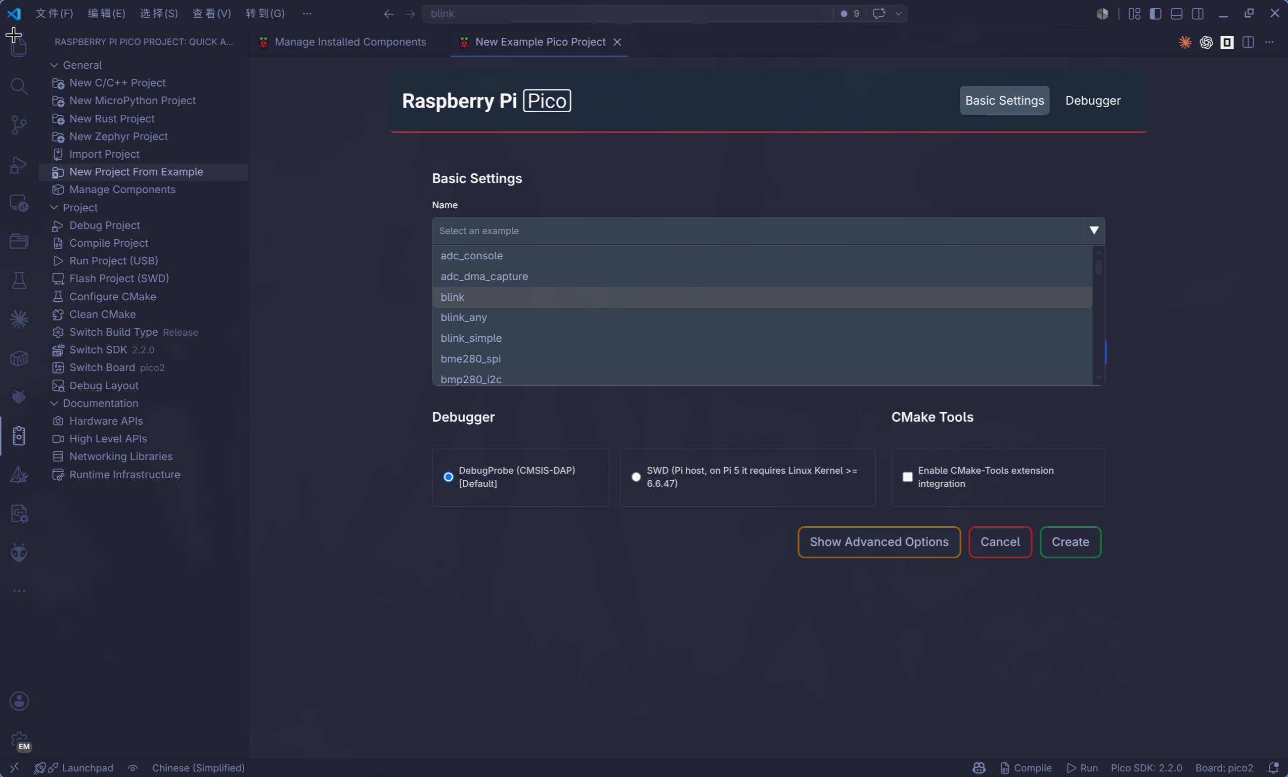
常见选项可以这样选:
- Board:Pico 2 选
pico2,Pico 2 W 选pico2_w。 - Toolchain:默认 C/C++ ARM 工具链;RISC-V 示例再选 RISC-V 工具链(可选作为验证)。
- Debugger: 使用默认的DebugProbe (CMSIS-DAP)
生成后项目里通常会出现:
my-pico-app/
├── CMakeLists.txt
├── pico_sdk_import.cmake
├── main.c
└── .vscode/
    ├── settings.json
    ├── tasks.json
    ├── launch.json
    └── cmake-kits.json
CMakeLists.txt 顶部会有一段插件管理块,类似:
# == DO NOT EDIT THE FOLLOWING LINES for the Raspberry Pi Pico VS Code Extension to work ==
set(sdkVersion ...)
set(toolchainVersion ...)
set(picotoolVersion ...)
set(picoVscode ${USERHOME}/.pico-sdk/cmake/pico-vscode.cmake)
if (EXISTS ${picoVscode})
    include(${picoVscode})
endif()
# ====================================================================================
这段代码是插件用来锁定 SDK 和工具链版本的。一般不要手改它;切换 SDK 或开发板时,优先使用插件命令:
Raspberry Pi Pico: Switch Pico SDK
Raspberry Pi Pico: Switch Board
编译、烧录和调试
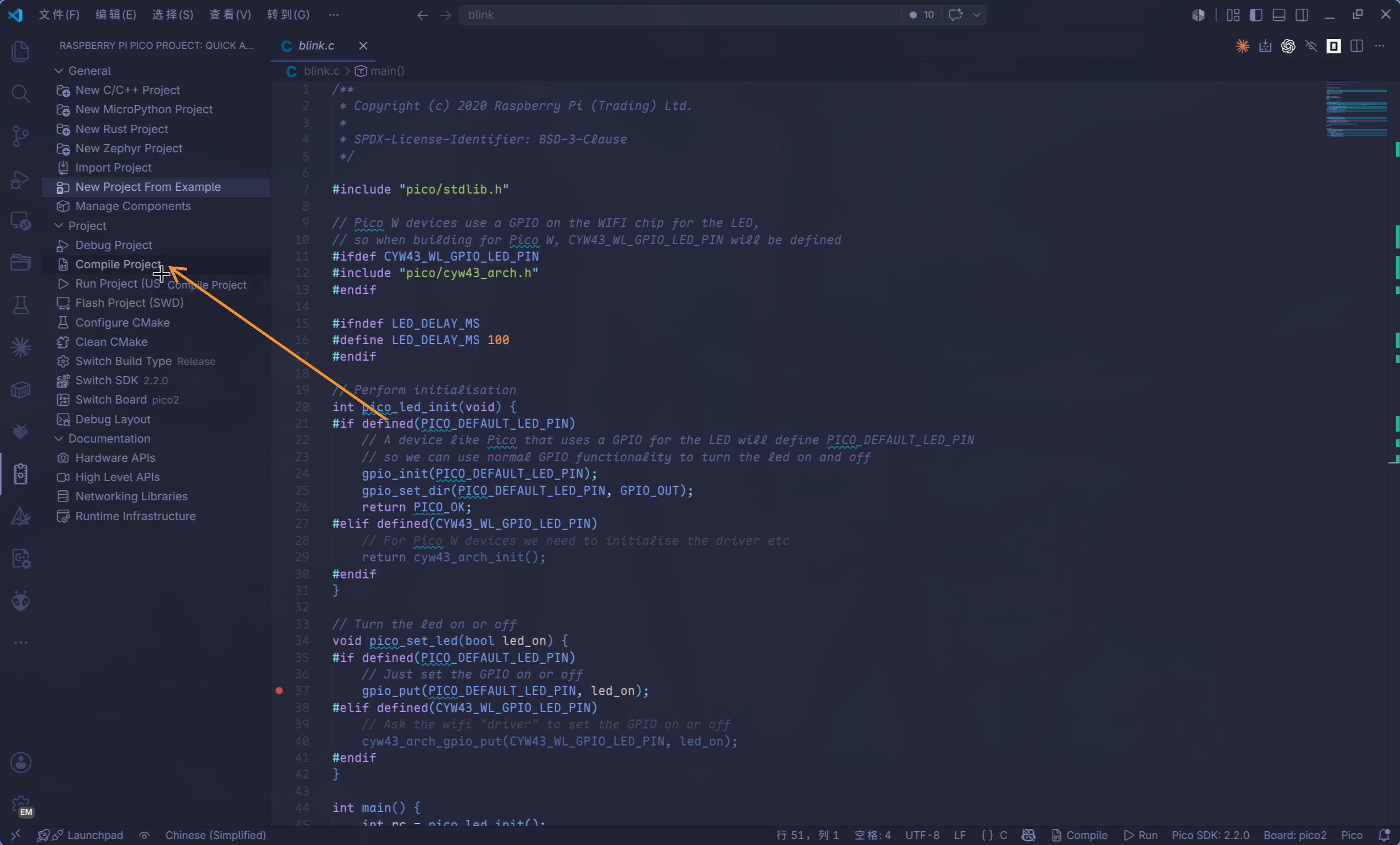
插件会在状态栏和命令面板里提供常用动作:
Raspberry Pi Pico: Compile Pico Project:编译当前项目。Raspberry Pi Pico: Run Pico Project (USB):通过 USB / picotool 烧录运行。Raspberry Pi Pico: Flash Pico Project (SWD):通过 Debug Probe / OpenOCD 烧录。Raspberry Pi Pico: Conditional Debugging:生成或打开调试配置。Raspberry Pi Pico: Debug Layout:切换到更适合调试的 VS Code 布局。
如果使用 Run Pico Project (USB),板子通常需要处于 BOOTSEL 模式,或者程序已经启用了 SDK 的 USB reset 支持。最稳妥的方式仍然是:
- 断开 Pico USB。
- 按住
BOOTSEL。 - 插入 USB。
- 松开
BOOTSEL。 - 在 VS Code 里运行
Run Pico Project (USB)。
如果使用 Flash Pico Project (SWD) 或调试功能,需要连接 Raspberry Pi Debug Probe,并确保 SWDIO、SWCLK、GND 接线正确。
常见问题
下载 SDK 或工具失败
插件需要访问 GitHub 下载 SDK、工具链和工具。如果提示版本获取失败或 GitHub API 限流,可以在 VS Code 设置里搜索 raspberry-pi-pico.githubToken,填入一个带 public_repo scope 的 classic PAT。
CMake Tools 提示选择 Kit
如果启用了 CMake Tools integration,选择插件生成的 Pico kit。普通项目推荐继续使用 Raspberry Pi Pico 插件的编译、运行、调试按钮,CMake Tools 主要负责配置和索引。
Linux 下 picotool 或 OpenOCD 权限错误
这通常不是 SDK 路径问题,而是 udev 规则或用户组没有生效。安装规则后需要重新插拔 Pico / Debug Probe;如果修改了用户组,通常还需要重新登录(注销再登录)。
安装ARM toolchain失败
Raspberry Pi Pico 插件安装 ARM toolchain 的逻辑比较简单:先根据所选 SDK 版本查 versionBundles.json,得到默认 toolchain 版本;再从 supportedToolchains.ini 里按当前平台选择下载地址;最后把压缩包下载到临时目录并解压到 ~/.pico-sdk/toolchain/<toolchainVersion>/。
以插件 0.20.0 和 Pico SDK 2.2.0 为例,默认 ARM toolchain 是:
14_2_Rel1
Linux x86_64 对应的下载地址是:
https://armkeil.blob.core.windows.net/developer/Files/downloads/gnu/14.2.rel1/binrel/arm-gnu-toolchain-14.2.rel1-x86_64-arm-none-eabi.tar.xz
插件内部的安装路径是:
~/.pico-sdk/toolchain/14_2_Rel1/
需要注意的是,ARM toolchain 不是从 GitHub 下载的,而是从 Arm 的 armkeil.blob.core.windows.net 下载。因此 raspberry-pi-pico.githubToken 只能缓解 GitHub API 限流,对 ARM toolchain 下载失败没有直接帮助。国内网络、代理、TLS、下载中断都可能导致插件安装失败;插件也没有断点续传,失败时常见表现就是 VS Code 弹出 Failed to download and install toolchain.。
如果插件下载经常失败,可以手动安装到插件期望的目录:
mkdir -p ~/.pico-sdk/toolchain/14_2_Rel1

wget -O /tmp/arm-gnu-toolchain-14.2.rel1-x86_64-arm-none-eabi.tar.xz \
  https://armkeil.blob.core.windows.net/developer/Files/downloads/gnu/14.2.rel1/binrel/arm-gnu-toolchain-14.2.rel1-x86_64-arm-none-eabi.tar.xz

tar -xJf /tmp/arm-gnu-toolchain-14.2.rel1-x86_64-arm-none-eabi.tar.xz \
  -C ~/.pico-sdk/toolchain/14_2_Rel1 \
  --strip-components=1

~/.pico-sdk/toolchain/14_2_Rel1/bin/arm-none-eabi-gcc --version
如果是 Linux ARM64 主机,下载地址要换成:
https://armkeil.blob.core.windows.net/developer/Files/downloads/gnu/14.2.rel1/binrel/arm-gnu-toolchain-14.2.rel1-aarch64-arm-none-eabi.tar.xz
插件判断“已安装”的条件也很宽松:只要 ~/.pico-sdk/toolchain/14_2_Rel1/ 存在并且目录非空,它就会跳过下载。因此如果上一次失败留下了不完整目录,插件可能误以为已经安装。遇到这种情况,先确认目录确实是坏的,再删除该版本目录后重新手动解压:
rm -rf ~/.pico-sdk/toolchain/14_2_Rel1
手动安装完成后,重新运行 Raspberry Pi Pico: Switch Pico SDK 或重新创建/导入项目,插件会复用这个目录。
手动配置开发环境(可选)
本节保留完全手动安装路线。它适合这些情况:
- 不使用 VS Code 插件,只想在终端里构建。
- 想把 SDK 和工具放在自己指定的位置,比如
~/embedded。 - 需要修改或调试 Pico SDK、picotool、OpenOCD 源码。
- 要在 CI、远程服务器或容器中固定一套工具链。
如果你已经安装了官方 VS Code 插件,并且 ~/.pico-sdk 已经配置好,优先使用 C 环境 里的插件复用路线即可。
目录约定
下面仍然沿用本书早期的手动目录:
mkdir -p ~/embedded
cd ~/embedded
如果你换成其他路径,后面的 PICO_SDK_PATH、PICO_TOOLCHAIN_PATH、OpenOCD 路径都要对应修改。
安装系统依赖
Debian / Ubuntu:
sudo apt install build-essential cmake git python3 pkg-config libusb-1.0-0-dev
sudo apt install gcc-arm-none-eabi binutils-arm-none-eabi libnewlib-arm-none-eabi
Arch Linux:
sudo pacman -S --needed base-devel cmake git python pkgconf libusb
sudo pacman -S --needed arm-none-eabi-gcc arm-none-eabi-binutils arm-none-eabi-newlib
验证交叉编译器:
arm-none-eabi-gcc --version
arm-none-eabi-objcopy --version
获取 Pico SDK
cd ~/embedded
git clone https://github.com/raspberrypi/pico-sdk

cd pico-sdk
git submodule update --init
设置环境变量:
export PICO_SDK_PATH="$HOME/embedded/pico-sdk"
如果希望每个新终端都自动生效,可以把上面这行加入 ~/.bashrc、~/.zshrc 或你正在使用的 shell 配置文件。
也可以不写入 shell 配置,而是在每次配置 CMake 时显式传入:
cmake -S . -B build -DPICO_SDK_PATH="$HOME/embedded/pico-sdk"
Important
PICO_SDK_PATH=/path/to/pico-sdk只会给当前 shell 变量赋值;如果没有export,CMake 子进程不一定能读到它。
构建并安装 picotool
picotool 用来查看 UF2/ELF 元数据,也可以在 Pico 处于 BOOTSEL 模式时烧录程序。推荐安装成完整 CMake package,而不是只复制二进制。
cd ~/embedded
git clone https://github.com/raspberrypi/picotool

cd picotool
cmake -S . -B build -DPICO_SDK_PATH="$PICO_SDK_PATH"
cmake --build build -j8
sudo cmake --install build
验证:
picotool version
安装后系统通常会有:
/usr/local/bin/picotool
/usr/local/lib/cmake/picotool/picotoolConfig.cmake
这样 Pico SDK 的 CMake 能找到本地 picotool,不会在配置项目时尝试下载。
配置 picotool udev 规则
Linux 默认可能不允许普通用户访问 BOOTSEL 模式下的 Pico。安装 udev 规则后,picotool 通常不需要 sudo。
cd ~/embedded/picotool
sudo install -m 0644 udev/60-picotool.rules /etc/udev/rules.d/60-picotool.rules
sudo udevadm control --reload-rules
如果规则引用 plugdev,但系统没有这个组:
getent group plugdev || sudo groupadd -r plugdev
sudo usermod -aG plugdev "$USER"
然后重新登录,或者重启电脑,并拔下重新插入 Pico。
构建 OpenOCD
对于 Pico 2 / RP2350,推荐使用 Raspberry Pi 官方维护的 openocd 下游分支,它包含 RP2350 支持。
Debian / Ubuntu:
sudo apt install build-essential pkg-config libusb-1.0-0-dev \
    libtool autoconf automake texinfo libftdi1-dev libhidapi-dev
Arch Linux:
sudo pacman -S --needed base-devel pkgconf libusb libtool autoconf \
    automake texinfo libftdi hidapi
克隆、构建并安装到 ~/embedded/openocd-install:
cd ~/embedded
git clone https://github.com/raspberrypi/openocd --branch rpi-common --depth=1

cd openocd
git submodule update --init --recursive
./bootstrap
./configure \
    --prefix="$HOME/embedded/openocd-install" \
    --enable-ftdi \
    --enable-cmsis-dap \
    --enable-internal-jimtcl \
    --enable-internal-libjaylink \
    --disable-werror
make -j8
make install
加入 PATH:
export PATH="$HOME/embedded/openocd-install/bin:$PATH"
验证:
openocd --version
test -f "$HOME/embedded/openocd-install/share/openocd/scripts/target/rp2350.cfg"
配置 OpenOCD udev 规则:
cd ~/embedded/openocd
sudo install -m 0644 contrib/60-openocd.rules /etc/udev/rules.d/60-openocd.rules
sudo udevadm control --reload-rules
sudo udevadm trigger
连接 Debug Probe 后验证:
openocd -f interface/cmsis-dap.cfg \
    -f target/rp2350.cfg \
    -c "adapter speed 5000" \
    -c "init; exit"
手动安装 RISC-V 工具链
Pico 2 的 RISC-V 模式需要单独的 RISC-V 裸机工具链。官方 SDK 文档推荐设置:
export PICO_TOOLCHAIN_PATH=/path/to/riscv/toolchain
export PICO_PLATFORM=rp2350-riscv
如果你使用发行版包,例如 Arch Linux:
sudo pacman -S riscv64-elf-gcc riscv64-elf-newlib riscv64-elf-binutils
构建时可以显式指定 triple:
cmake -S . -B build-riscv \
    -DPICO_BOARD=pico2 \
    -DPICO_PLATFORM=rp2350-riscv \
    -DPICO_GCC_TRIPLE=riscv64-elf
cmake --build build-riscv -j
如果使用官方插件下载到 ~/.pico-sdk/toolchain/ 的 RISC-V 工具链,则不需要这一步,直接看 RISC-V 初探。
安装环境说明
树莓派 Pico 在 Windows、macOS 和 Linux 上提供统一的开发体验,本书基于 Linux 平台完成开发工作。
C SDK 环境说明
现在推荐的路线是:
- 用官方 VS Code 插件安装和管理 SDK、工具链与工具组件。
- 在 VS Code 内通过插件按钮编译、烧录、调试。
- 在普通终端里也复用插件安装到
~/.pico-sdk的同一套工具。
如果你想完全手动克隆 SDK、构建 picotool 和 OpenOCD,请看 手动配置开发环境(可选)。
Rust 开发所需的 rustup target、probe-rs、Cargo runner 等内容放在 Rust 环境 中。
插件已经安装了什么
安装 Raspberry Pi Pico VS Code 插件 并完成首次项目创建/导入后,工具通常位于:
~/.pico-sdk/
├── sdk/              # Pico SDK
├── toolchain/        # ARM / RISC-V 裸机交叉编译器
├── cmake/            # 插件管理的 CMake
├── ninja/            # 插件管理的 Ninja
├── picotool/         # BOOTSEL / UF2 工具
├── openocd/          # Raspberry Pi 下游 OpenOCD
├── tools/            # pioasm 等 SDK 工具
├── examples/         # 插件示例缓存,未必是完整 pico-examples
└── cmake/pico-vscode.cmake
你可以先查看本机已经安装的版本:
find "$HOME/.pico-sdk" -maxdepth 2 -type d | sort
下面的命令以这组版本为例:
sdk/2.2.0
toolchain/14_2_Rel1
toolchain/RISCV_ZCB_RPI_2_2_0_3
picotool/2.2.0-a4
cmake/v3.31.5
ninja/v1.12.1
openocd/0.12.0+dev
在终端中使用 ~/.pico-sdk
VS Code 插件生成的项目会在 .vscode/settings.json 中自动设置终端环境;如果你在普通终端里编译本书示例,可以手动导出下面这些变量:
export PICO_SDK_VERSION=2.2.0
export PICO_TOOLCHAIN_VERSION=14_2_Rel1
export PICOTOOL_VERSION=2.2.0-a4
export CMAKE_VERSION=v3.31.5
export NINJA_VERSION=v1.12.1
export OPENOCD_VERSION=0.12.0+dev

export PICO_SDK_PATH="$HOME/.pico-sdk/sdk/$PICO_SDK_VERSION"
export PICO_TOOLCHAIN_PATH="$HOME/.pico-sdk/toolchain/$PICO_TOOLCHAIN_VERSION"
export PICO_CMAKE="$HOME/.pico-sdk/cmake/$CMAKE_VERSION/bin/cmake"
export PICO_NINJA="$HOME/.pico-sdk/ninja/$NINJA_VERSION/ninja"
export PICO_OPENOCD="$HOME/.pico-sdk/openocd/$OPENOCD_VERSION/openocd"
export PICO_OPENOCD_SCRIPTS="$HOME/.pico-sdk/openocd/$OPENOCD_VERSION/scripts"

export picotool_DIR="$HOME/.pico-sdk/picotool/$PICOTOOL_VERSION/picotool"
export pioasm_DIR="$HOME/.pico-sdk/tools/$PICO_SDK_VERSION/pioasm"

export PATH="$PICO_TOOLCHAIN_PATH/bin:$picotool_DIR:$(dirname "$PICO_CMAKE"):$(dirname "$PICO_NINJA"):$(dirname "$PICO_OPENOCD"):$PATH"
建议把这段保存成你自己的 shell 片段,例如 ~/.config/pico-env.sh,需要时执行,或者直接写入bashrc中也可以:
source ~/.config/pico-env.sh
Important
这里的变量值要和
~/.pico-sdk里的实际版本一致。插件更新 SDK 或工具链后,重新检查并更新这几个版本变量。
验证工具
检查 SDK:
test -f "$PICO_SDK_PATH/pico_sdk_init.cmake"
test -f "$PICO_SDK_PATH/external/pico_sdk_import.cmake"
检查 CMake 和 Ninja:
"$PICO_CMAKE" --version
"$PICO_NINJA" --version
检查 ARM 交叉编译器:
arm-none-eabi-gcc --version
arm-none-eabi-objcopy --version
检查 picotool:
picotool version
没有进入 BOOTSEL 模式时,下面这条命令提示找不到设备是正常的:
picotool info
检查 OpenOCD:
"$PICO_OPENOCD" --version
test -f "$PICO_OPENOCD_SCRIPTS/target/rp2350.cfg"
构建官方示例验证环境
插件可以通过 Raspberry Pi Pico: New Example Pico Project 创建示例项目。之前在vscode环境配置时候,已经建立过示例项目blink,直接cd过去
-
使用插件命令进行构建
-
终端中手动构建:
"$PICO_CMAKE" -S . -B build -G Ninja \
    -DCMAKE_MAKE_PROGRAM="$PICO_NINJA" \
    -DPICO_BOARD=pico2 \
    -DPICO_SDK_PATH="$PICO_SDK_PATH" \
    -DPICO_TOOLCHAIN_PATH="$PICO_TOOLCHAIN_PATH" \
    -Dpicotool_DIR="$picotool_DIR" \
    -Dpioasm_DIR="$pioasm_DIR"
构建
blink:"$PICO_CMAKE" --build build --target blink -j8
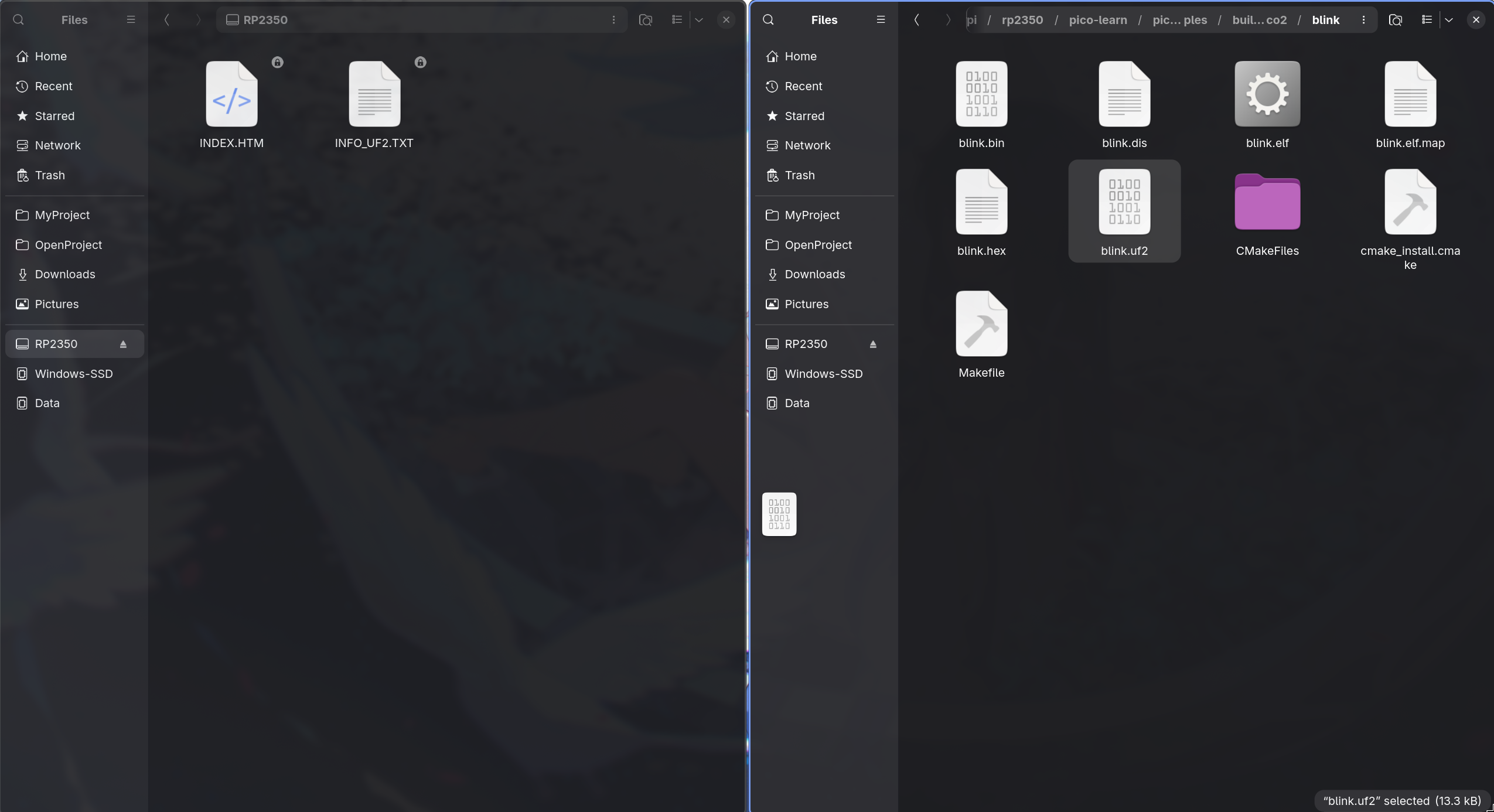
成功后会生成:
build/blink/blink.elf
build/blink/blink.uf2
build/blink/blink.bin
blink.uf2 可以拖拽到 BOOTSEL 模式下出现的 RP2350 磁盘,也可以使用 picotool 烧录:
picotool load -u -v -x build/blink/blink.uf2
如果已经连接 Raspberry Pi Debug Probe,可以使用插件安装的 OpenOCD 烧录 ELF:
"$PICO_OPENOCD" -s "$PICO_OPENOCD_SCRIPTS" \
    -f interface/cmsis-dap.cfg \
    -f target/rp2350.cfg \
    -c "adapter speed 5000" \
    -c "program build/blink/blink.elf verify reset exit"
成功时会看到:
** Programming Finished **
** Verify Started **
** Verified OK **
** Resetting Target **
配置 udev 规则
Linux 上如果 picotool 或 OpenOCD 提示权限不足,使用sudo有嫌弃需要输入密码。
那可以安装 udev 规则。
插件安装的预编译
picotool目录里不一定带规则文件,所以可以从对应官方仓库获取,或者按 手动配置开发环境(可选) 先克隆源码后安装规则。
安装后一般还需要重新插拔 Pico / Debug Probe。如果修改了用户组,需要重新登录或重启。
常见问题
SDK location was not specified
错误示例:
SDK location was not specified. Please set PICO_SDK_PATH
解决方式:
export PICO_SDK_PATH="$HOME/.pico-sdk/sdk/2.2.0"
或者给 CMake 显式传参:
"$PICO_CMAKE" -S . -B build \
    -DPICO_SDK_PATH="$HOME/.pico-sdk/sdk/2.2.0"
Compiler arm-none-eabi-gcc not found
先确认工具链路径和 PATH:
echo "$PICO_TOOLCHAIN_PATH"
which arm-none-eabi-gcc
如果 which 找不到,重新执行本章的环境变量片段。
No installed picotool found
如果 CMake 配置时提示找不到 picotoolConfig.cmake,请显式传入插件安装的 package 路径:
-Dpicotool_DIR="$HOME/.pico-sdk/picotool/2.2.0-a4/picotool"
这个目录里应该包含:
picotoolConfig.cmake
picotoolConfigVersion.cmake
No accessible RP-series devices
错误示例:
No accessible RP-series devices in BOOTSEL mode were found.
通常说明 Pico 没有进入 BOOTSEL 模式,或者 udev 规则没有对当前设备生效。按住 BOOTSEL 插入 USB,并重新插拔设备。如果刚刚修改过用户组,先重新登录。
Failed to initialise libUSB
如果在容器、远程沙箱或受限环境中运行 picotool,可能会看到:
ERROR: Failed to initialise libUSB
这通常不是 Pico SDK 安装问题,而是当前运行环境没有 USB 设备访问权限。请在普通终端中再次运行 picotool info 确认。
OpenOCD 找不到 target/rp2350.cfg
使用插件安装的 OpenOCD 时,建议显式传入脚本根目录:
"$PICO_OPENOCD" -s "$PICO_OPENOCD_SCRIPTS" \
    -f interface/cmsis-dap.cfg \
    -f target/rp2350.cfg \
    -c "adapter speed 5000" \
    -c "init; exit"
如果直接运行系统里的 openocd,它可能没有 RP2350 支持。优先使用 ~/.pico-sdk/openocd/.../openocd,或者按手动章节构建 Raspberry Pi 下游分支。
安装环境说明
树莓派pico在 Windows、macOS 和 Linux 上提供统一的开发体验,本书就基于linux平台完成开发工作。
Rust 环境搭建
本章只覆盖 Rust 开发、烧录和调试需要的工具。C SDK、arm-none-eabi-gcc、PICO_SDK_PATH 等内容放在 C SDK 环境 中。
对于本书的 Rust 示例,最常用的流程有两种:
- 使用
picotool通过 BOOTSEL 模式烧录。 - 使用
probe-rs通过 Debug Probe 烧录和调试。
由于使用 Rust 做 Pico 嵌入式开发的人目前仍然比 C/C++ 少,虽然 VS Code 的 Raspberry Pi Pico 插件可以直接新建 Rust 项目,但它生成的模板走的是 rp-hal 生态,而不是本书主讲的 Embassy 生态,所以本书不直接沿用 Pico VS Code 插件生成的 Rust 模板,自己手动配置项目更有利于学习。
安装rust
本书的 Rust 示例项目以 Embassy 为主线,示例工程位于:
/home/ruoshui/Documents/MyProject/raspberrypi/rp2350/pico-learn/pico2-quick
该项目使用 embassy-rp 和 embassy-executor,默认构建 Pico 2;如果要构建 Pico 2 W,需要启用 pico2w feature。安装环境时重点准备三类工具:
- Rust 主机工具链:
rustc、cargo、rustup。 - RP2350 ARM 编译目标:
thumbv8m.main-none-eabihf。 - 烧录/调试工具:BOOTSEL 路线使用
picotool,Debug Probe 路线使用probe-rs、cargo flash、cargo embed。
安装 Rust 工具链
推荐使用 rustup 管理 Rust。Linux 下可以直接使用官方安装脚本:
curl --proto '=https' --tlsv1.2 -sSf https://sh.rustup.rs | sh
source "$HOME/.cargo/env"
安装后使用稳定版工具链,并更新到当前版本:
rustup default stable
rustup update
rustc --version
cargo --version
本书主线使用 Pico 2 的 ARM Cortex-M33 内核,所以需要添加:
rustup target add thumbv8m.main-none-eabihf
如果后续要尝试 RP2350 的 RISC-V 内核,再额外添加:
rustup target add riscv32imac-unknown-none-elf
检查目标是否已经安装:
rustup target list --installed | grep -E 'thumbv8m.main-none-eabihf|riscv32imac-unknown-none-elf'
安装烧录和调试工具
如果使用 BOOTSEL 模式烧录,示例项目的 .cargo/config.toml 已经把 cargo run 配成调用:
picotool load -u -v -x -t elf
因此先确认 picotool 可用:
picotool version
如果命令不存在,可以先按 C SDK 环境章节安装 picotool,或者使用 Raspberry Pi Pico VS Code 插件安装在 ~/.pico-sdk/picotool/ 下的预编译版本。
如果使用 Raspberry Pi Debug Probe 调试或烧录,安装 probe-rs 工具链:
curl -LsSf https://github.com/probe-rs/probe-rs/releases/latest/download/probe-rs-tools-installer.sh | sh
source "$HOME/.cargo/env"

probe-rs --version
cargo flash --version
cargo embed --version
Linux 下还需要配置 udev 规则,否则普通用户可能无法访问 BOOTSEL 设备或 Debug Probe。picotool 和 probe-rs 的 udev 配置分别见后续小节。
验证示例项目
进入本书使用的 Embassy 示例项目:
cd /home/ruoshui/Documents/MyProject/raspberrypi/rp2350/pico-learn/pico2-quick
编译 Pico 2 默认版本:
cargo build-pico2
编译 Pico 2 W 版本:
cargo build-pico2w
如果 Pico 2 以 BOOTSEL 模式连接,可以用 picotool 路线运行:
cargo run-pico2
Pico 2 W 对应:
cargo run-pico2w
如果使用 Debug Probe,可以用 probe-rs 路线烧录或调试:
cargo flash-pico2
cargo embed-pico2
Pico 2 W 对应:
cargo flash-pico2w
cargo embed-pico2w
Rust 目标平台
Pico 2 使用 RP2350 芯片。RP2350 同时包含 ARM Cortex-M33 和 Hazard3 RISC-V 内核。本书主要使用 ARM target:
rustup target add thumbv8m.main-none-eabihf
如果你要尝试 RISC-V 模式,也可以添加:
rustup target add riscv32imac-unknown-none-elf
检查已安装目标:
rustup target list --installed
probe-rs - 烧录与调试工具
probe-rs 是 Rust 嵌入式生态常用的烧录和调试工具。使用 Raspberry Pi Debug Probe、CMSIS-DAP、J-Link、ST-Link 等调试探针时,可以用它来下载程序、查看 RTT 日志和调试。
使用官方安装脚本:
curl -LsSf https://github.com/probe-rs/probe-rs/releases/latest/download/probe-rs-tools-installer.sh | sh
安装后检查:
probe-rs --version
cargo flash --version
cargo embed --version
最新说明以 probe-rs 官方文档 为准。
配置 probe-rs 的 udev 规则
默认情况下,Linux 上的调试探针通常只能由 root 访问。安装 udev 规则后,普通用户也可以使用 probe-rs。
curl -Lsf https://probe.rs/files/69-probe-rs.rules -o /tmp/69-probe-rs.rules
sudo install -m 0644 /tmp/69-probe-rs.rules /etc/udev/rules.d/69-probe-rs.rules
sudo udevadm control --reload-rules
如果系统没有 plugdev 组,同样需要创建并加入:
getent group plugdev || sudo groupadd -r plugdev
sudo usermod -aG plugdev "$USER"
完成后拔下并重新插入 Debug Probe。修改用户组后需要重新登录。
检查是否能枚举调试探针:
probe-rs list
没有连接 Debug Probe 时,看到 No debug probes were found. 是正常的;如果出现权限错误,优先检查 udev 规则是否已重载、当前用户是否已经重新登录。
Cargo runner
本书示例通常在 .cargo/config.toml 中配置 runner:
[target.'cfg(all(target_arch = "arm", target_os = "none"))']
runner = "picotool load -u -v -x -t elf"

[build]
target = "thumbv8m.main-none-eabihf"
这样执行 cargo run 时,Cargo 会先编译 ELF,然后调用:
picotool load -u -v -x -t elf <your-program.elf>
如果你已经安装了 udev 规则,runner 中不应该再写 sudo picotool ...。把 sudo 写进 runner 会让自动化构建和 IDE 集成变复杂。
使用 Debug Probe 时,可以改用 probe-rs:
runner = "probe-rs run --chip RP2350"
也可以直接使用:
cargo flash --chip RP2350 --release
cargo embed --chip RP2350 --release
验证环境
可以用一个 Pico 2 / Pico 2W 的 Rust 示例验证环境:
git clone https://github.com/Zhruoshui/pico2-quick
cd pico2-quick
cargo build
如果 Pico 2 / Pico 2W 已经以 BOOTSEL 模式连接:
cargo run --release # for Pico 2
cargo run --release --no-default-features --features pico2w # for Pico 2W
也可以单独检查 picotool 是否能访问 USB:
picotool info
没有连接 BOOTSEL 设备时,No accessible RP-series devices in BOOTSEL mode were found. 是正常结果。若在容器或沙箱中运行,可能会看到 Failed to initialise libUSB,这通常是运行环境没有 USB 访问权限,不一定是系统安装错误。
快速入门 for C
本章从一个空目录开始,手写一个最小 Pico 2 / Pico 2 W C 工程。环境仍然使用官方 VS Code 插件安装到 ~/.pico-sdk 的 SDK、CMake、Ninja、ARM 工具链、picotool 和 OpenOCD;我们只是不用插件向导生成代码,而是自己把项目结构写出来。
如果你只是想快速生成工程,可以直接使用 VS Code 官方插件 里的 Raspberry Pi Pico: New Pico Project。本章的目的,是让你看清楚一个 Pico C 工程最小需要哪些文件,以及每一步构建命令到底在做什么。
准备终端环境
先确认已经完成 C 环境 中的插件工具链配置。普通终端里需要先导入环境变量:
source ~/.config/pico-env.sh
如果你把那段环境变量写进了 ~/.bashrc 或 ~/.zshrc,打开新终端后可以直接检查:
echo "$PICO_SDK_PATH"
echo "$PICO_TOOLCHAIN_PATH"
"$PICO_CMAKE" --version
"$PICO_NINJA" --version
arm-none-eabi-gcc --version
picotool version
如果这些命令里有空输出或 command not found,先回到 C 环境 修正 ~/.pico-sdk 版本变量。
Pico 2 和 Pico 2 W 的差异
还记得在 Pico 2 和 Pico 2 W 的差异 中提到的吗?
Note
Pico 2 和 Pico 2 W 都基于 RP2350,但板载 LED 接法不同:
- Pico 2 的 LED 在 RP2350 的普通 GPIO 上,SDK 会定义
PICO_DEFAULT_LED_PIN。- Pico 2 W 的 LED 在 CYW43 无线芯片上,SDK 会定义
CYW43_WL_GPIO_LED_PIN,并且需要链接pico_cyw43_arch_none。
因此,本章会写一份同时兼容 Pico 2 和 Pico 2 W 的代码,通过 -DPICO_BOARD=pico2 或 -DPICO_BOARD=pico2_w 切换开发板。
建立目录
建立一个目录来放置工程文件:
mkdir pico2-plugin-blink
cd pico2-plugin-blink
touch CMakeLists.txt main.c
把 SDK 提供的导入脚本复制到当前项目:
cp "$PICO_SDK_PATH/external/pico_sdk_import.cmake" .
这个文件是 Pico SDK 的 CMake 入口脚本。它会根据 PICO_SDK_PATH 找到真正的 SDK。
最终项目结构是:
pico2-plugin-blink/
├── CMakeLists.txt
├── main.c
└── pico_sdk_import.cmake
写 CMakeLists.txt
把 CMakeLists.txt 写成下面这样:
cmake_minimum_required(VERSION 3.13)

include(pico_sdk_import.cmake)

project(pico2_plugin_blink C CXX ASM)

set(CMAKE_C_STANDARD 11)
set(CMAKE_CXX_STANDARD 17)

pico_sdk_init()

add_executable(pico2_plugin_blink
    main.c
)

target_link_libraries(pico2_plugin_blink
    pico_stdlib
)

if (PICO_CYW43_SUPPORTED)
    target_link_libraries(pico2_plugin_blink
        pico_cyw43_arch_none
    )
endif()

pico_add_extra_outputs(pico2_plugin_blink)

set(PICOTOOL picotool CACHE FILEPATH "Path to picotool executable")

add_custom_target(pico2_plugin_blink_run
    COMMAND ${PICOTOOL} load -u -v -x -t elf $<TARGET_FILE:pico2_plugin_blink>
    DEPENDS pico2_plugin_blink
    USES_TERMINAL
)

set(OPENOCD openocd CACHE FILEPATH "Path to OpenOCD executable")
set(OPENOCD_SCRIPTS "" CACHE PATH "Path to OpenOCD scripts")
set(OPENOCD_SCRIPT_ARGS "")
if (OPENOCD_SCRIPTS)
    list(APPEND OPENOCD_SCRIPT_ARGS -s ${OPENOCD_SCRIPTS})
endif()

add_custom_target(pico2_plugin_blink_probe
    COMMAND ${OPENOCD}
            ${OPENOCD_SCRIPT_ARGS}
            -f interface/cmsis-dap.cfg
            -f target/rp2350.cfg
            -c "adapter speed 5000"
            -c "program $<TARGET_FILE:pico2_plugin_blink> verify reset exit"
    DEPENDS pico2_plugin_blink
    USES_TERMINAL
)
这里有几个关键点:
include(pico_sdk_import.cmake)必须在project()之前。project(... C CXX ASM)要启用 C、C++ 和汇编,因为 Pico SDK 的启动代码会用到它们。pico_sdk_init()必须在创建可执行 target 之前调用。pico_add_extra_outputs()会在 ELF 之外生成.uf2、.bin、.hex等文件。pico2_plugin_blink_run使用picotool通过 BOOTSEL / USB 烧录。pico2_plugin_blink_probe使用 OpenOCD 通过 Debug Probe / SWD 烧录。
写 main.c
把 main.c 写成下面这样:
#include <stdbool.h>

#include "pico/stdlib.h"

#if defined(CYW43_WL_GPIO_LED_PIN)
#include "pico/cyw43_arch.h"
#endif

#define LED_DELAY_MS 250

static int board_led_init(void) {
#if defined(PICO_DEFAULT_LED_PIN)
    gpio_init(PICO_DEFAULT_LED_PIN);
    gpio_set_dir(PICO_DEFAULT_LED_PIN, GPIO_OUT);
    return PICO_OK;
#elif defined(CYW43_WL_GPIO_LED_PIN)
    return cyw43_arch_init();
#else
    return -1;
#endif
}

static void board_led_put(bool on) {
#if defined(PICO_DEFAULT_LED_PIN)
    gpio_put(PICO_DEFAULT_LED_PIN, on);
#elif defined(CYW43_WL_GPIO_LED_PIN)
    cyw43_arch_gpio_put(CYW43_WL_GPIO_LED_PIN, on);
#endif
}

int main(void) {
    if (board_led_init() != PICO_OK) {
        return 1;
    }

    while (true) {
        board_led_put(true);
        sleep_ms(LED_DELAY_MS);

        board_led_put(false);
        sleep_ms(LED_DELAY_MS);
    }
}
这份代码可以同时构建 Pico 2 和 Pico 2 W:
- Pico 2 会走
PICO_DEFAULT_LED_PIN分支,直接控制普通 GPIO。 - Pico 2 W 会走
CYW43_WL_GPIO_LED_PIN分支,先初始化 CYW43,再控制无线芯片上的 LED。
编译 Pico 2
配置构建目录:
"$PICO_CMAKE" -S . -B build-pico2 -G Ninja \
    -DCMAKE_MAKE_PROGRAM="$PICO_NINJA" \
    -DPICO_BOARD=pico2 \
    -DPICO_SDK_PATH="$PICO_SDK_PATH" \
    -DPICO_TOOLCHAIN_PATH="$PICO_TOOLCHAIN_PATH" \
    -Dpicotool_DIR="$picotool_DIR" \
    -Dpioasm_DIR="$pioasm_DIR" \
    -DPICOTOOL="$picotool_DIR/picotool" \
    -DOPENOCD="$PICO_OPENOCD" \
    -DOPENOCD_SCRIPTS="$PICO_OPENOCD_SCRIPTS"
构建:
"$PICO_CMAKE" --build build-pico2 -j8
生成的 UF2 文件在:
build-pico2/pico2_plugin_blink.uf2
编译 Pico 2 W
配置构建目录:
"$PICO_CMAKE" -S . -B build-pico2w -G Ninja \
    -DCMAKE_MAKE_PROGRAM="$PICO_NINJA" \
    -DPICO_BOARD=pico2_w \
    -DPICO_SDK_PATH="$PICO_SDK_PATH" \
    -DPICO_TOOLCHAIN_PATH="$PICO_TOOLCHAIN_PATH" \
    -Dpicotool_DIR="$picotool_DIR" \
    -Dpioasm_DIR="$pioasm_DIR" \
    -DPICOTOOL="$picotool_DIR/picotool" \
    -DOPENOCD="$PICO_OPENOCD" \
    -DOPENOCD_SCRIPTS="$PICO_OPENOCD_SCRIPTS"
构建:
"$PICO_CMAKE" --build build-pico2w -j8
生成的 UF2 文件在:
build-pico2w/pico2_plugin_blink.uf2
Pico 2 W 的构建会自动链接 pico_cyw43_arch_none,否则 cyw43_arch_init() 和 cyw43_arch_gpio_put() 会链接失败。
使用 BOOTSEL 运行
Pico 2 和 Pico 2 W 的 UF2 烧录方式相同:
- 断开 Pico 的 USB 连接。
- 按住
BOOTSEL按钮不放。 - 保持按住按钮,用 USB 线把 Pico 接到电脑。
- 电脑识别到 BOOTSEL 设备后,松开按钮。
- 复制对应的 UF2 文件,或者使用
picotool烧录。
拖拽或复制 UF2。Pico 2:
cp build-pico2/pico2_plugin_blink.uf2 /run/media/$USER/RP2350/
Pico 2 W:
cp build-pico2w/pico2_plugin_blink.uf2 /run/media/$USER/RP2350/
如果你的系统挂载路径不是 /run/media/$USER/RP2350/,可以先用文件管理器或 lsblk 确认实际路径。复制完成后,U 盘会自动断开,板子重启,板载 LED 开始闪烁。
也可以直接用 picotool 烧录 ELF。Pico 2:
"$PICO_CMAKE" --build build-pico2 --target pico2_plugin_blink_run
Pico 2 W:
"$PICO_CMAKE" --build build-pico2w --target pico2_plugin_blink_run
这种方式仍然需要 Pico 处于 BOOTSEL 模式。如果看到:
No accessible RP-series devices in BOOTSEL mode were found.
通常说明板子没有进入 BOOTSEL 模式,或者 Linux udev 规则还没有生效。
另外你也可以直接把对应文件拖到 RP2350 盘里:
使用 Debug Probe 烧录
如果你连接了 Raspberry Pi Debug Probe,就不需要按 BOOTSEL。目标板仍然需要通过 USB 或外部电源供电,并且 Debug Probe 的 SWDIO、SWCLK、GND 要和 Pico 正确连接。
Pico 2:
"$PICO_CMAKE" --build build-pico2 --target pico2_plugin_blink_probe
Pico 2 W:
"$PICO_CMAKE" --build build-pico2w --target pico2_plugin_blink_probe
成功时会看到类似:
** Programming Finished **
** Verify Started **
** Verified OK **
** Resetting Target **
如果命令提示找不到 CMSIS-DAP 设备,通常需要检查 Debug Probe 的 USB 连接、SWD 接线,以及当前用户是否有访问调试器的权限。
用 VS Code 插件接管这个项目
上面的工程是手写 CMake 项目,不依赖插件生成 .vscode/ 配置。你仍然可以让插件接管它:
Ctrl+Shift+P
Raspberry Pi Pico: Import Pico Project
导入后插件会补充 .vscode/settings.json、tasks.json、launch.json 等文件,并在 CMakeLists.txt 顶部加入插件管理块。之后可以用插件按钮:
Compile Pico ProjectRun Pico Project (USB)Flash Pico Project (SWD)
如果你只是想理解 CMake 和命令行,本章前面的终端流程已经足够;如果你想日常在 VS Code 里点按钮构建和调试,再执行导入。
常见问题
PICO_SDK_PATH 为空
如果复制 pico_sdk_import.cmake 或配置 CMake 时失败,先检查:
echo "$PICO_SDK_PATH"
test -f "$PICO_SDK_PATH/external/pico_sdk_import.cmake"
普通终端里通常是忘了执行:
source ~/.config/pico-env.sh
arm-none-eabi-gcc not found
检查插件工具链是否在 PATH 中:
echo "$PICO_TOOLCHAIN_PATH"
which arm-none-eabi-gcc
如果 which 找不到,重新导入 C 环境 中的 ~/.pico-sdk 环境变量。
picotool 找不到或无权限
先确认 CMake 配置时传入了:
-Dpicotool_DIR="$picotool_DIR"
-DPICOTOOL="$picotool_DIR/picotool"
如果命令能找到 picotool,但访问 BOOTSEL 设备失败,通常是 Pico 没进 BOOTSEL 模式,或者 Linux udev 规则没有生效。
Pico 2 W 链接失败
如果 Pico 2 W 构建时出现 cyw43_arch_init 或 cyw43_arch_gpio_put 未定义,通常说明没有链接 CYW43 库。确认 CMakeLists.txt 里有:
if (PICO_CYW43_SUPPORTED)
    target_link_libraries(pico2_plugin_blink
        pico_cyw43_arch_none
    )
endif()
并且配置时使用的是:
-DPICO_BOARD=pico2_w
快速入门 for Rust
我们同样用 Rust 运行一个闪灯程序。在 Rust 中,我们使用 Embassy 库。Embassy 是 Rust 嵌入式生态中的异步框架,它可以让我们用 async/await 写微控制器程序。后面会再详细介绍这个框架,现在先有个印象即可。
Pico 2 和 Pico 2 W 的差异
还记得在Pico 2 和 Pico 2 W 的差异中提及的吗?
Note
Pico 2 和 Pico 2 W 都基于 RP2350,但它们的板载 LED 接法不同:
- Pico 2 的闪灯代码非常直接,只需要配置
PIN_25为输出引脚;- Pico 2 W 则必须先初始化 CYW43 芯片,再通过 CYW43 的 GPIO 控制 LED。
示例项目已经用 Cargo feature 来做类似 C 语言条件编译的板型切换:
- 默认 feature 是
pico2。 - 使用
--no-default-features --features pico2w切换到 Pico 2 W。
克隆示例项目
git clone https://github.com/Zhruoshui/pico2-quick
cd pico2-quick
项目里已经配置好了常用命令别名:
cargo build-pico2
cargo run-pico2
cargo flash-pico2
cargo embed-pico2

cargo build-pico2w
cargo run-pico2w
cargo flash-pico2w
cargo embed-pico2w
代码核心
Pico 2 的 LED 是普通 GPIO,所以核心代码很短:
#[embassy_executor::main]
async fn main(_spawner: Spawner) {
    let p = embassy_rp::init(Default::default());
    let mut led = Output::new(p.PIN_25, Level::Low);

    loop {
        led.set_high();
        Timer::after_millis(100).await;

        led.set_low();
        Timer::after_millis(100).await;
    }
}
Pico 2 W 的完整代码会长很多,因为它需要初始化 CYW43 固件、NVRAM、PIO SPI 和后台 runner。
在示例项目中,最终点亮 Pico 2 W LED 的代码是:
#![allow(unused)]
fn main() {
control.gpio_set(0, true).await;
Timer::after_millis(100).await;

control.gpio_set(0, false).await;
Timer::after_millis(100).await;
}
这里的 0 指的是 CYW43 芯片上的 GPIO0。
只编译
先确认代码可以编译。
Pico 2:
cargo build-pico2
Pico 2 W:
cargo build-pico2w
等价的原始 Cargo 命令分别是:
cargo build --release
cargo build --release --no-default-features --features pico2w
使用 BOOTSEL 运行
cargo run 这条路径使用的是 picotool,也就是 BOOTSEL 模式。
步骤如下:
- 断开 Pico 的 USB 连接。
- 按住
BOOTSEL按钮不放。 - 保持按住按钮,用 USB 线把 Pico 接到电脑。
- 电脑识别到 BOOTSEL 设备后,松开按钮。
- 运行对应命令
Pico 2:
cargo run-pico2
Pico 2 W:
cargo run-pico2w
如果你看到类似下面的错误:
No accessible RP-series devices in BOOTSEL mode were found.
通常说明板子当前没有进入 BOOTSEL 模式,或者系统的 udev 规则还没有对当前用户生效。先重新按住 BOOTSEL 插入 USB,再试一次。
另外你也可以直接把对应文件拖到 RP2350 盘里即可,不过能自动化是最好的:
使用 Debug Probe 烧录
如果你连接了 Debug Probe,就不需要按 BOOTSEL。这时使用 cargo flash 或 cargo embed。
Pico 2:
cargo flash-pico2
cargo embed-pico2
Pico 2 W:
cargo flash-pico2w
cargo embed-pico2w
两者区别是:
cargo flash-*:只烧录并运行程序。cargo embed-*:烧录后打开 RTT,可以看到defmt日志输出。
这个示例程序会输出类似下面的日志:
[INFO] Pico 2 W CYW43 LED blink
[INFO] led on
[INFO] led off
Pico 2 W 在启动时会初始化 CYW43,所以底层初始化流程比 Pico 2 多;但示例项目已经关闭了不必要的 CYW43 调试日志,cargo embed-pico2w 里主要看到的就是应用自己的 led on/off 输出。
命令选择速查
| 场景 | Pico 2 | Pico 2 W |
|---|---|---|
| 只编译 | cargo build-pico2 | cargo build-pico2w |
| BOOTSEL / picotool | cargo run-pico2 | cargo run-pico2w |
| Debug Probe 烧录 | cargo flash-pico2 | cargo flash-pico2w |
| Debug Probe + RTT 日志 | cargo embed-pico2 | cargo embed-pico2w |
运行成功后,板载 LED 会持续闪烁。
基于 pico-examples 的 C 项目模板
pico-examples 是 Raspberry Pi 官方维护的 Pico SDK 示例仓库。可以把它当成 Pico C 工程的参考模板,学习官方推荐的 CMake 组织方式,然后把其中一个示例裁剪成自己的工程。
官方插件可以通过 Raspberry Pi Pico: New Example Pico Project 创建示例项目。如果你想在命令行里阅读和构建完整 pico-examples,建议把官方示例仓库克隆到自己的工作区;构建工具仍然使用 ~/.pico-sdk 里的 SDK、CMake、Ninja 和工具链:
mkdir -p ~/pico
cd ~/pico
git clone https://github.com/raspberrypi/pico-examples.git
cd pico-examples
先编译官方 blink闪灯程序
如果你使用的是 Pico 2:
cmake -S . -B build-pico2 \
    -DPICO_BOARD=pico2

cmake --build build-pico2 --target blink -j8
如果你使用的是 Pico 2 W:
cmake -S . -B build-pico2w \
    -DPICO_BOARD=pico2_w

cmake --build build-pico2w --target blink -j8
构建成功后,blink 的输出文件在对应构建目录下:
build-pico2/blink/blink.elf
build-pico2/blink/blink.uf2
build-pico2/blink/blink.bin
-DPICO_BOARD=pico2 或 -DPICO_BOARD=pico2_w 会让 SDK 选择对应开发板配置。Pico SDK 默认面向 RP2040;对于 Pico 2 / Pico 2 W,推荐显式传入 PICO_BOARD,这样 SDK 会自动选择 RP2350 平台和板级引脚定义。
pico-examples 的顶层结构
pico-examples 的根目录大致可以分成三类文件:
pico-examples/
├── CMakeLists.txt
├── pico_sdk_import.cmake
├── pico_extras_import_optional.cmake
├── example_auto_set_url.cmake
├── blink/
├── hello_world/
├── gpio/
├── pwm/
├── spi/
└── ...
其中:
CMakeLists.txt是整个示例仓库的唯一顶层入口。pico_sdk_import.cmake用来定位并导入 Pico SDK,必须在project()之前include。pico_extras_import_optional.cmake用来可选导入pico-extras,普通 LED、GPIO、PWM、SPI 示例不一定需要它。example_auto_set_url.cmake是官方示例仓库自己的辅助脚本,用来给生成的程序写入示例 URL。自己的项目通常可以不带它。blink/、gpio/、pwm/、spi/这些目录只是示例分类,是否参与构建由顶层CMakeLists.txt决定。
顶层 CMakeLists.txt 的构建次序
阅读 pico-examples/CMakeLists.txt 时,最重要的是顺序。它不是随便写的,Pico SDK 的 CMake 工程需要按下面的顺序组织。
第一步,声明 CMake 版本,然后在 project() 之前导入 SDK:
cmake_minimum_required(VERSION 3.12)

include(pico_sdk_import.cmake)
include(pico_extras_import_optional.cmake)

project(pico_examples C CXX ASM)
这里的关键点是:include(pico_sdk_import.cmake) 必须出现在 project() 之前。这个脚本会根据 PICO_SDK_PATH 找到 SDK,并导入 SDK 提供的初始化脚本。
第二步,设置语言标准、检查 SDK 版本,并初始化 SDK:
set(CMAKE_C_STANDARD 11)
set(CMAKE_CXX_STANDARD 17)

if (PICO_SDK_VERSION_STRING VERSION_LESS "2.2.0")
    message(FATAL_ERROR "Raspberry Pi Pico SDK version 2.2.0 (or later) required.")
endif()

pico_sdk_init()
pico_sdk_init() 必须在创建应用 target 之前调用。调用后,pico_stdlib、hardware_pwm、hardware_spi、pico_add_extra_outputs() 这些 SDK target 和函数才准备好,子目录里的示例才能正常链接它们。
第三步,顶层开始把示例目录加入构建:
add_subdirectory_exclude_platforms(blink)
add_subdirectory_exclude_platforms(blink_simple)
add_subdirectory_exclude_platforms(hello_world)
add_subdirectory_exclude_platforms() 是官方示例自己定义的小函数。它会先检查当前 PICO_PLATFORM 是否被排除,如果不排除,再调用真正的 add_subdirectory()。
简化后可以理解为:
function(add_subdirectory_exclude_platforms NAME)
    # 如果当前平台不支持这个示例,就跳过。
    add_subdirectory(${NAME})
endfunction()
第四步,加入更多外设示例目录。当前官方示例的顶层顺序是:
blink
blink_simple
hello_world
adc
binary_info
bootloaders
clocks
cmake
dcp
divider
dma
encrypted
flash
gpio
hstx
i2c
interp
multicore
otp
picoboard
pico_w
pio
pwm
reset
rtc
spi
status_led
system
timer
uart
universal
usb
watchdog
sha
freertos
这说明 CMake 的配置过程是从根目录进入每个示例目录,再由子目录继续进入更小的叶子示例。例如:
pico-examples/CMakeLists.txt
└── add_subdirectory(pwm)
    └── pwm/CMakeLists.txt
        ├── add_subdirectory(hello_pwm)
        ├── add_subdirectory(led_fade)
        └── add_subdirectory(measure_duty_cycle)
有些分类目录还会先检查 SDK target 是否存在。比如 pwm/CMakeLists.txt 会检查 hardware_pwm,spi/CMakeLists.txt 会检查 hardware_spi。如果当前平台不支持,就在 CMake 配置阶段跳过对应示例。
Note
官方顶层文件里的
add_compile_options(-Wall ...)放在blink、blink_simple、hello_world之后。CMake 的顺序会影响后续目录继承到的编译选项。你自己写项目时,如果希望所有 target 都使用某些编译选项,最好在创建 target 之前设置,或者更明确地使用target_compile_options()。
blink 示例的叶子 CMakeLists.txt
blink/CMakeLists.txt 是一个很适合作为模板的最小示例:
add_executable(blink
    blink.c
)

target_link_libraries(blink pico_stdlib)

if (PICO_CYW43_SUPPORTED)
    target_link_libraries(blink pico_cyw43_arch_none)
endif()

pico_add_extra_outputs(blink)

example_auto_set_url(blink)
这个文件只负责定义 blink 这个 target。它假设 SDK 已经在顶层被初始化,所以它可以直接使用:
add_executable():声明要生成的可执行程序。target_link_libraries(... pico_stdlib):链接 Pico SDK 的基础库,包含 GPIO、时间、stdio、断言等常用功能。PICO_CYW43_SUPPORTED:如果目标板支持 CYW43,比如 Pico 2 W,就额外链接pico_cyw43_arch_none。pico_add_extra_outputs():在 ELF 之外生成.uf2、.bin、.hex、.map等文件。example_auto_set_url():官方示例专用,自己的项目可以删掉。
blink 还额外定义了两个自定义目标:
add_custom_target(blink_run
    COMMAND picotool load -u -v -x -t elf $<TARGET_FILE:blink>
    DEPENDS blink
    USES_TERMINAL
)

set(OPENOCD openocd CACHE FILEPATH "Path to OpenOCD executable")
set(OPENOCD_SCRIPTS "" CACHE PATH "Path to OpenOCD scripts")
set(OPENOCD_SCRIPT_ARGS "")
if (OPENOCD_SCRIPTS)
    list(APPEND OPENOCD_SCRIPT_ARGS -s ${OPENOCD_SCRIPTS})
endif()

add_custom_target(blink_probe
    COMMAND ${OPENOCD}
            ${OPENOCD_SCRIPT_ARGS}
            -f interface/cmsis-dap.cfg
            -f target/rp2350.cfg
            -c "adapter speed 5000"
            -c "program $<TARGET_FILE:blink> verify reset exit"
    DEPENDS blink
    USES_TERMINAL
)
这里的 DEPENDS blink 很重要。它告诉 CMake:运行 blink_run 或 blink_probe 之前,必须先把 blink 构建出来。
构建并烧录可以写成:
cmake --build build-pico2 --target blink_run
或者使用 Debug Probe:
cmake --build build-pico2 --target blink_probe
OPENOCD 默认使用 PATH 中的 openocd。如果你使用官方插件安装的 OpenOCD,可以在配置时传入 -DOPENOCD=$HOME/.pico-sdk/openocd/0.12.0+dev/openocd 和 -DOPENOCD_SCRIPTS=$HOME/.pico-sdk/openocd/0.12.0+dev/scripts;如果你走手动路线,则改成自己的 OpenOCD 安装路径。
复用成自己的工程
如果你只是想建立一个自己的 Pico C 项目,不需要复制整个 pico-examples。建议只保留最小结构:
my-pico-app/
├── CMakeLists.txt
├── pico_sdk_import.cmake
└── src/
    └── main.c
可以从 SDK 复制导入脚本:
mkdir -p my-pico-app/src
cd my-pico-app

cp "$PICO_SDK_PATH/external/pico_sdk_import.cmake" .
touch CMakeLists.txt src/main.c
然后把 CMakeLists.txt 写成下面这样:
cmake_minimum_required(VERSION 3.13)

include(pico_sdk_import.cmake)

project(my_pico_app C CXX ASM)

set(CMAKE_C_STANDARD 11)
set(CMAKE_CXX_STANDARD 17)

pico_sdk_init()

add_executable(my_pico_app
    src/main.c
)

target_link_libraries(my_pico_app
    pico_stdlib
)

if (PICO_CYW43_SUPPORTED)
    target_link_libraries(my_pico_app
        pico_cyw43_arch_none
    )
endif()

pico_add_extra_outputs(my_pico_app)

add_custom_target(my_pico_app_run
    COMMAND picotool load -u -v -x -t elf $<TARGET_FILE:my_pico_app>
    DEPENDS my_pico_app
    USES_TERMINAL
)

set(OPENOCD openocd CACHE FILEPATH "Path to OpenOCD executable")
set(OPENOCD_SCRIPTS "" CACHE PATH "Path to OpenOCD scripts")
set(OPENOCD_SCRIPT_ARGS "")
if (OPENOCD_SCRIPTS)
    list(APPEND OPENOCD_SCRIPT_ARGS -s ${OPENOCD_SCRIPTS})
endif()

add_custom_target(my_pico_app_probe
    COMMAND ${OPENOCD}
            ${OPENOCD_SCRIPT_ARGS}
            -f interface/cmsis-dap.cfg
            -f target/rp2350.cfg
            -c "adapter speed 5000"
            -c "program $<TARGET_FILE:my_pico_app> verify reset exit"
    DEPENDS my_pico_app
    USES_TERMINAL
)
这个文件保留了官方模板里最关键的构建顺序:
include(pico_sdk_import.cmake)在project()之前。project(... C CXX ASM)启用 C、C++ 和汇编。pico_sdk_init()在所有add_executable()之前。add_executable()创建自己的程序。target_link_libraries()链接 SDK 库。pico_add_extra_outputs()生成 UF2 等烧录文件。add_custom_target()把烧录命令接到 CMake 构建目标上。
构建自己的工程
Pico 2:
cmake -S . -B build-pico2 \
    -DPICO_BOARD=pico2

cmake --build build-pico2 -j8
Pico 2 W:
cmake -S . -B build-pico2w \
    -DPICO_BOARD=pico2_w

cmake --build build-pico2w -j8
生成文件位于:
build-pico2/my_pico_app.elf
build-pico2/my_pico_app.uf2
build-pico2/my_pico_app.bin
使用 BOOTSEL + picotool 烧录:
cmake --build build-pico2 --target my_pico_app_run
使用 Debug Probe 烧录:
cmake --build build-pico2 --target my_pico_app_probe
如果 openocd 不在 PATH 中,重新配置时显式传入路径。使用官方插件环境时:
cmake -S . -B build-pico2 \
    -DPICO_BOARD=pico2 \
    -DOPENOCD=$HOME/.pico-sdk/openocd/0.12.0+dev/openocd \
    -DOPENOCD_SCRIPTS=$HOME/.pico-sdk/openocd/0.12.0+dev/scripts
如果你是完全手动安装,则把 OPENOCD 改成自己的安装位置,例如 ~/embedded/openocd-install/bin/openocd。
什么时候继续使用 pico-examples
当你需要某个外设的官方写法时,继续回到 pico-examples 查对应目录即可。例如:
- LED / 板载灯:
blink/ - USB 串口输出:
hello_world/usb/ - GPIO 中断:
gpio/hello_gpio_irq/ - PWM:
pwm/hello_pwm/ - SPI:
spi/ - I2C:
i2c/ - UART:
uart/ - Watchdog:
watchdog/
查示例时建议先看叶子目录的 CMakeLists.txt,再看 .c 文件。因为 CMake 文件会告诉你这个示例依赖哪些 SDK 库,例如 hardware_pwm、hardware_spi、hardware_i2c。把代码复制进自己的工程后,也要把对应库加入 target_link_libraries()。
例如你从 pwm/hello_pwm 复制代码,就需要链接:
target_link_libraries(my_pico_app
    pico_stdlib
    hardware_pwm
)
从 spi/max7219_32x8_spi 复制代码,则需要链接:
target_link_libraries(my_pico_app
    pico_stdlib
    hardware_spi
)
这样使用 pico-examples,它就不只是“能跑的例子“,而是你后续写 Pico C 工程时最可靠的一组官方模板。
使用 cargo-generate 创建项目模板
“cargo-generate 是一个开发者工具,它可以把已有的 git 仓库作为模板,帮助你快速创建并启动一个新的 Rust 项目。”
更多信息可以阅读 cargo-generate GitHub 项目。
前置条件
开始之前,请确保你已经安装了以下工具:
- Rust
- cargo-generate,用于生成项目模板。
由于 cargo-generate 需要 OpenSSL 开发包,请先安装它:
sudo apt install libssl-dev
可以使用下面的命令安装 cargo-generate:
cargo install cargo-generate
第 1 步:生成项目
运行下面的命令,通过模板生成项目:
cargo generate --git https://github.com/ImplFerris/pico2-template.git --tag v0.3.2
命令执行后,会提示你回答几个问题:
- Project name:为你的项目命名。
- HAL choice:可以在
embassy和rp-hal之间选择。
第 2 步:默认 LED 闪烁示例
默认情况下,生成出来的项目会包含一个简单的 LED 闪烁示例。代码结构大致如下:
src/main.rs:包含默认的闪灯逻辑。
Cargo.toml:包含所选 HAL 需要的依赖。
第 3 步:选择 HAL 并修改代码
项目生成后,你可以选择保留默认的 LED 闪烁代码,也可以删除它,并根据所选的 HAL 替换成自己的代码。
删除不需要的代码
你可以从 src/main.rs 中删除闪灯逻辑,并换成自己的代码。根据项目需要,调整 Cargo.toml 中的依赖和项目结构即可。
Pico 2 / Pico 2W 也可以使用RISC-V核心编程,RISC-V架构支持通过动态切换Cortex-M33(Armv8-M)处理器与Hazard3(RV32IMAC+)处理器来实现。RISC-V核心支持通过SWD进行调试,并且可以使用与ARM核心相同的SDK进行编程。
RISC-V 构建和运行
在 RISC-V 模式下,程序运行在 Pico 2 的 Hazard3 处理器上。C 与 Rust 的构建方式分别见下。
Important
本书重点介绍 ARM。某些示例在 RISC-V 模式下工作前可能需要进行修改。为简便起见,建议在阅读本书时遵循 ARM 工作流程。
建议严格遵循sdk中的说明来使用:https://github.com/raspberrypi/pico-sdk#risc-v-support-on-rp2350
同时RISC-V的学习演示可以看:http://github.com/mytechnotalent/RP2350_Blink_Driver_RISCV
for c
如果你已经通过官方 VS Code 插件安装了 RISC-V 工具链,可以直接复用 ~/.pico-sdk/toolchain/ 下的工具。先确认本机目录名:
ls "$HOME/.pico-sdk/toolchain"
下面以插件安装的 RISCV_ZCB_RPI_2_2_0_3 为例。RISC-V 模式不需要改动源码,也不需要改 CMakeLists.txt,同一个 pico2-manual-blink 工程,只在配置时把平台切到 rp2350-riscv:
export PICO_SDK_PATH="$HOME/.pico-sdk/sdk/2.2.0"
export PICO_TOOLCHAIN_PATH="$HOME/.pico-sdk/toolchain/RISCV_ZCB_RPI_2_2_0_3"
export PATH="$PICO_TOOLCHAIN_PATH/bin:$PATH"

# 构建(Hazard3 RISC-V),产物在 build-riscv/
cmake -S . -B build-riscv \
    -DPICO_BOARD=pico2 \
    -DPICO_PLATFORM=rp2350-riscv \
    -DPICO_TOOLCHAIN_PATH="$PICO_TOOLCHAIN_PATH" \
    -DPICO_COMPILER=pico_riscv_gcc_zcb_zcmp
cmake --build build-riscv -j
生成的 UF2 文件在 build-riscv/pico2_manual_blink.uf2。
Note
RISC-V 需要单独的编译器,ARM 的
arm-none-eabi-gcc不能用。官方插件安装的是riscv32-unknown-elf-*工具链,并且pico_riscv_gcc_zcb_zcmp会启用适合 RP2350 Hazard3 的 RISC-V 编译器配置。Hazard3 没有硬件 FPU,浮点走软件库(soft-float)。
如果你没有使用官方插件,也可以按 手动配置开发环境(可选) 安装发行版或官方预编译 RISC-V 工具链,再把 PICO_TOOLCHAIN_PATH 和 PICO_PLATFORM=rp2350-riscv 指向你的安装路径。
烧录方式与 ARM 完全相同(BOOTSEL + 复制 UF2):
cp build-riscv/pico2_manual_blink.uf2 /run/media/$USER/RP2350/
for rust
切换到rust项目中
# 构建程序
cargo build --target=riscv32imac-unknown-none-elf
按照上面描述的相同 BOOTSEL 步骤进行操作。
# 烧录程序
cargo run --target=riscv32imac-unknown-none-elf
Async In Embedded Rust
When I first started this book, I wrote most of the examples using rp-hal only. In this revision, I have rewritten the book to focus mainly on async programming with Embassy. The official Embassy book already has good documentation, but I want to give a short introduction here. Let’s have a brief look at async and understand why it’s so valuable in embedded systems.
Imagine You’re Cooking Dinner
If you’re familiar with concurrency and async concepts, you don’t need this analogy; Embassy is basically like Tokio for embedded systems, providing an async runtime. If you’re new to async, let me explain with this analogy.
You are making dinner and you put water on to boil. Instead of standing there watching, you chop vegetables. You glance at the pot occasionally, and when you see bubbles, you’re ready for the next step. Now while the main dish cooks, you prepare a side dish in another pan. You even check a text message on your phone. You’re one person constantly moving between tasks, checking what needs attention, doing work whenever something is ready, and never just standing idle waiting.

That’s async programming. You’re the executor, constantly deciding what needs attention. Each cooking task is an async operation. The stove does its heating without you watching it. That’s the non-blocking wait. You don’t freeze in place staring at boiling water. You go do other productive work and come back when it’s ready. The key insight is efficient orchestration: one person (the executor), multiple waiting tasks, and you’re always doing something useful by switching your attention to whatever is ready right now. This is exactly what async programming does for your microcontroller.
Different Approaches
In embedded systems, your microcontroller spends a lot of time waiting. It waits for a button press, for a timer to expire, or for an LED to finish blinking for a set duration. Without async, you have two main approaches.
Blocking
The first approach is blocking code. Your program literally stops and waits. If you’re waiting for a button press, your code sits in a loop checking if the button state has changed. During this time, your microcontroller can’t do anything else. It can’t blink an LED, it can’t check other buttons, it can’t respond to timers. All of your processor’s power is wasted in a tight loop asking “is it ready yet?” over and over again.
Interrupt
The second approach is using interrupts directly. When hardware events happen, like a button being pressed or a timer expiring, the interrupt handler runs. This is better because your main code can keep running, but interrupt-based code quickly becomes complex and error-prone. You need to carefully manage shared state between your main code and interrupt handlers.
Do not worry about interrupts for now. We will go into them in more depth in later chapters.
Async
Async programming gives you the best of both worlds. Your code looks clean and sequential, like blocking code, but it doesn’t actually block. When you await something, your code says “I need to wait for this, but feel free to do other work in the meantime.” The async runtime, which Embassy provides for us, handles all the complexity of switching between tasks efficiently.
How Async Works in Rust
When you write an async function in Rust, you use the async keyword before fn. Inside that function, you can use the await keyword on operations that might take time. Here’s what it looks like:
#![allow(unused)]
fn main() {
async fn blink_led(mut led: Output<'static>) {
    loop {
        led.set_high();
        Timer::after_millis(500).await;
        led.set_low();
        Timer::after_millis(500).await;
    }
}
}
The important part is the .await. When you write Timer::after_millis(500).await, you’re telling the runtime “I need to wait 500 milliseconds, but I don’t need the CPU during that time.” The runtime can then go run other tasks. When the 500 milliseconds are up, your task resumes right where it left off.
Think back to our cooking analogy. When you put something on the stove and walk away, you’re essentially “awaiting” it to be ready. You do other things, and when it’s done, you return to that task. Just like you act as the executor in the kitchen, keeping track of what needs attention and when, the async runtime plays the same role for your program.
Embassy
Embassy is one of the popular async runtime that makes all of this work in embedded Rust. It provides the executor that manages your tasks, handles hardware interrupts.
Executor
When you use #[embassy_executor::main], Embassy automatically sets everything up - it runs your tasks, puts the CPU to sleep when everything is waiting, and wakes it up when hardware events occur. The Executor is the coordinator that decides which task to poll when. The executor maintains a queue of tasks that are ready to run. When a task hits await and yields, the executor moves to the next ready task. When there are no tasks ready to run, the executor puts the CPU to sleep. Interrupts wake the executor back up, which then polls any tasks that became ready.
RTIC
RTIC (Real-Time Interrupt-driven Concurrency) is another popular framework for embedded Rust. Unlike Embassy, which provides an async runtime along with hardware drivers, RTIC focuses only on execution and scheduling. In RTIC, you declare tasks with fixed priorities and shared resources upfront, and the framework checks at compile time that resources are shared safely without data races. Higher-priority tasks can preempt lower-priority ones, and the scheduling is handled by hardware interrupts, which makes timing very predictable. This makes RTIC a good fit for hard real-time systems where precise control and determinism matter. You can refer the official RTIC book for more info.
In this book, we will mainly use Embassy.
Blinking an External LED
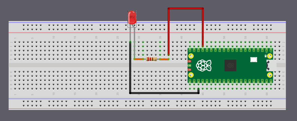
From now on, we’ll use more external parts with the Pico. Before we get there, it helps to get comfortable with simple circuits and how to connect components to the Pico’s pins. In this chapter, we’ll start with something basic: blinking an LED that’s connected outside the board.
Hardware Requirements
- LED
- Resistor
- Jumper wires
Components Overview
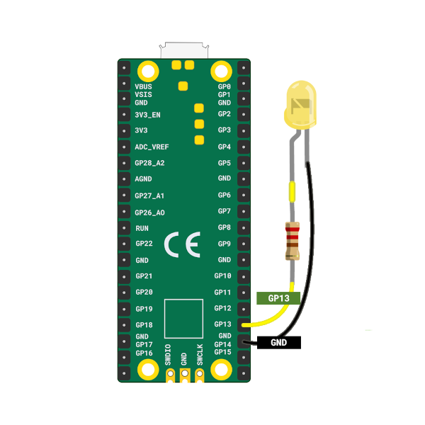
-
LED: An LED (Light Emitting Diode) lights up when current flows through it. The longer leg (anode) connects to positive, and the shorter leg (cathode) connects to ground. We’ll connect the anode to GP13 (with a resistor) and the cathode to GND.
-
Resistors: A resistor limits the current in a circuit to protect components like LEDs. Its value is measured in Ohms (Ω). We’ll use a 330 ohm resistor to safely power the LED.
| Pico Pin | Wire | Component |
|---|---|---|
| GPIO 13 |
|
Resistor |
| Resistor |
|
Anode (long leg) of LED |
| GND |
|
Cathode (short leg) of LED |
You can connect the Pico to the LED using jumper wires directly, or you can place everything on a breadboard. If you’re unsure about the hardware setup, you can also refer the Raspberry Pi guide.
Tip
On the Pico, the pin labels are on the back of the board, which can feel inconvenient when plugging in wires. I often had to check the pinout diagram whenever I wanted to use a GPIO pin. Use the Raspberry Pi logo on the front as a reference point and match it with the pinout diagram to find the correct pins. Pin positions 2 and 39 are also printed on the front and can serve as additional guides.
LED Blink - Simulation
In this simulation I set the default delay to 5000 milliseconds so the animation is calmer and easier to follow. You can lower it to something like 500 milliseconds to see the LED blink more quickly. When we run the actual code on the Pico, we will use a 500 millisecond delay.
C 实现
Blink an External LED on the Raspberry Pi Pico with Embedded Rust
Let’s start by creating our project. We’ll use cargo-generate and use the template we prepared for this book.
In your terminal, type:
cargo generate --git https://github.com/ImplFerris/pico2-template.git --tag v0.3.2
You will be asked a few questions:
-
For the project name, you can give anything. We will use
external-led. -
Next, it asks us “Which HAL?” We should choose
embassy. -
Then, it will ask whether we want to enable
defmtlogging. This works only if we use a debug probe, so you can choose based on your setup. Anyway we are not going to write any log in this exercise.
Imports
Most of the required imports are already in the project template. For this exercise, we only need to add the Output struct and the Level enum from gpio:
#![allow(unused)]
fn main() {
use embassy_rp::gpio::{Level, Output};
}
While writing the main code, your editor will normally suggest missing imports. If something is not suggested or you see an error, check the full code section and add the missing imports from there.
Main Logic
The code is almost the same as the quick start example. The only change is that we now use GPIO 13 instead of GPIO 25. GPIO 13 is where we connected the LED (through a resistor).
Let’s add these code the main function :
#![allow(unused)]
fn main() {
let mut led = Output::new(p.PIN_13, Level::Low);

loop {
    led.set_high(); // Turn on the LED
    Timer::after_millis(500).await;

    led.set_low(); // Turn off the LED
    Timer::after_millis(500).await;
}
}
We are using the Output struct here because we want to send signals from the Pico to the LED. We set up GPIO 13 as an output pin and start it in the low (off) state.
Note
If you want to read signals from a component (like a button or sensor), you’ll need to configure the GPIO pin as Input instead.
Then we call set_high() and set_low() on the pin with a delay between them. This switches the pin between high and low, which turns the LED on and off.
The Full code
Here is the complete code for reference:
#![no_std]
#![no_main]

use embassy_executor::Spawner;
use embassy_rp as hal;
use embassy_rp::block::ImageDef;
use embassy_rp::gpio::{Level, Output};
use embassy_time::Timer;

//Panic Handler
use panic_probe as _;
// Defmt Logging
use defmt_rtt as _;

/// Tell the Boot ROM about our application
#[unsafe(link_section = ".start_block")]
#[used]
pub static IMAGE_DEF: ImageDef = hal::block::ImageDef::secure_exe();

#[embassy_executor::main]
async fn main(_spawner: Spawner) {
    let p = embassy_rp::init(Default::default());

    let mut led = Output::new(p.PIN_13, Level::Low);

    loop {
        led.set_high(); // Turn on the LED
        Timer::after_millis(500).await;

        led.set_low(); // Turn off the LED
        Timer::after_millis(500).await;
    }
}

// Program metadata for `picotool info`.
// This isn't needed, but it's recomended to have these minimal entries.
#[unsafe(link_section = ".bi_entries")]
#[used]
pub static PICOTOOL_ENTRIES: [embassy_rp::binary_info::EntryAddr; 4] = [
    embassy_rp::binary_info::rp_program_name!(c"external-led"),
    embassy_rp::binary_info::rp_program_description!(c"your program description"),
    embassy_rp::binary_info::rp_cargo_version!(),
    embassy_rp::binary_info::rp_program_build_attribute!(),
];

// End of file
Clone the existing project
You can clone the project I created and navigate to the external-led folder:
git clone https://github.com/ImplFerris/pico2-embassy-projects
cd pico2-embassy-projects/external-led
How to Run?
You refer the “Running The Program” section
Blinky Example using rp-hal
In the previous section, we used Embassy. We keep the same circuit and wiring. For this example, we switch to rp-hal to show how both approaches look. You can choose Embassy if you want async support, or rp-hal if you prefer the blocking style. In this book, we will mainly use Embassy.
We will create a new project again with cargo-generate and the same template.
In your terminal, type:
cargo generate --git https://github.com/ImplFerris/pico2-template.git --tag v0.3.2
When it asks you to select HAL, choose “rp-hal” this time.
Imports
The template already includes most imports. For this example, we need to add the OutputPin trait from embedded-hal:
#![allow(unused)]
fn main() {
// Embedded HAL trait for the Output Pin
use embedded_hal::digital::OutputPin;
}
This trait provides the set_high() and set_low() methods we’ll use to control the LED.
Main Logic
If you compare this with the Embassy version, there’s not much difference in how the LED is toggled. The main difference is in how the delay works. Embassy uses async and await, which lets the program pause without blocking and allows other tasks to run in the background. rp-hal uses a blocking delay, which stops the program until the time has passed.
#![allow(unused)]
fn main() {
let mut led_pin = pins.gpio13.into_push_pull_output();

loop {
    led_pin.set_high().unwrap();
    timer.delay_ms(200);

    led_pin.set_low().unwrap();
    timer.delay_ms(200);
}
}
Full code
#![no_std]
#![no_main]

use embedded_hal::delay::DelayNs;
use hal::block::ImageDef;
use rp235x_hal as hal;

//Panic Handler
use panic_probe as _;
// Defmt Logging
use defmt_rtt as _;

// Embedded HAL trait for the Output Pin
use embedded_hal::digital::OutputPin;

/// Tell the Boot ROM about our application
#[unsafe(link_section = ".start_block")]
#[used]
pub static IMAGE_DEF: ImageDef = hal::block::ImageDef::secure_exe();
/// External high-speed crystal on the Raspberry Pi Pico 2 board is 12 MHz.
/// Adjust if your board has a different frequency
const XTAL_FREQ_HZ: u32 = 12_000_000u32;

#[hal::entry]
fn main() -> ! {
    // Grab our singleton objects
    let mut pac = hal::pac::Peripherals::take().unwrap();

    // Set up the watchdog driver - needed by the clock setup code
    let mut watchdog = hal::Watchdog::new(pac.WATCHDOG);

    // Configure the clocks
    //
    // The default is to generate a 125 MHz system clock
    let clocks = hal::clocks::init_clocks_and_plls(
        XTAL_FREQ_HZ,
        pac.XOSC,
        pac.CLOCKS,
        pac.PLL_SYS,
        pac.PLL_USB,
        &mut pac.RESETS,
        &mut watchdog,
    )
    .ok()
    .unwrap();

    // The single-cycle I/O block controls our GPIO pins
    let sio = hal::Sio::new(pac.SIO);

    // Set the pins up according to their function on this particular board
    let pins = hal::gpio::Pins::new(
        pac.IO_BANK0,
        pac.PADS_BANK0,
        sio.gpio_bank0,
        &mut pac.RESETS,
    );

    let mut timer = hal::Timer::new_timer0(pac.TIMER0, &mut pac.RESETS, &clocks);

    let mut led_pin = pins.gpio13.into_push_pull_output();

    loop {
        led_pin.set_high().unwrap();
        timer.delay_ms(200);

        led_pin.set_low().unwrap();
        timer.delay_ms(200);
    }
}

// Program metadata for `picotool info`.
// This isn't needed, but it's recomended to have these minimal entries.
#[unsafe(link_section = ".bi_entries")]
#[used]
pub static PICOTOOL_ENTRIES: [hal::binary_info::EntryAddr; 5] = [
    hal::binary_info::rp_cargo_bin_name!(),
    hal::binary_info::rp_cargo_version!(),
    hal::binary_info::rp_program_description!(c"your program description"),
    hal::binary_info::rp_cargo_homepage_url!(),
    hal::binary_info::rp_program_build_attribute!(),
];
Clone the existing project
You can clone the project I created and navigate to the external-led folder:
git clone https://github.com/ImplFerris/pico2-rp-projects
cd pico2-rp-projects/external-led
From std to no_std
We have successfully flashed and run our first program, which creates a blinking effect. However, we have not yet explored the code or the project structure in detail. In this section, we will recreate the same project from scratch. I will explain each part of the code and configuration along the way. Are you ready for the challenge?
Tip
If you find this chapter overwhelming, especially if you’re just working on a hobby project, feel free to skip it for now. You can come back to it later after building some fun projects and working through exercises.
Create a Fresh Project
We will start by creating a standard Rust binary project. Use the following command:
#![allow(unused)]
fn main() {
cargo new pico-from-scratch
}
At this stage, the project will contain the usual files as expected.
├── Cargo.toml
└── src
    └── main.rs
Our goal is to reach the following final project structure:
├── build.rs
├── .cargo
│   └── config.toml
├── Cargo.toml
├── memory.x
├── rp235x_riscv.x
├── src
│   └── main.rs
Cross Compilation
You probably know about cross compilation already. In this section, we’ll explore how this works and what it means to deal with things like target triples. In simple terms, cross compilation is building programs for different machine than the one you’re using.
You can write code on one computer and make programs that run on totally different computers. For example, you can work on Linux and build .exe files for Windows. You can even target bare-metal microcontrollers like the RP2350, ESP32, or STM32.
TL;DR
We have to use either “thumbv8m.main-none-eabihf” or “riscv32imac-unknown-none-elf” as the target when building our binary for the Pico 2.
cargo build --target thumbv8m.main-none-eabihfWe can also configure the target in
.cargo/config.tomlso that we don’t need to type it every time.
Building for Your Host System
Let’s say we are on a Linux machine. When you run the usual build command, Rust compiles your code for your current host platform, which in this case is Linux:
cargo build
You can confirm what kind of binary it just produced using the file command:
file ./target/debug/pico-from-scratch
This will give an output like the following. This tells you it is a 64-bit ELF binary, dynamically linked, and built for Linux.
./target/debug/pico-from-scratch: ELF 64-bit LSB pie executable, x86-64, version 1 (SYSV), dynamically linked, interpreter /lib64/ld-linux-x86-64.so.2, Build...
Cross compiling for Windows
Now let’s say you want to build a binary for Windows without leaving your Linux machine. That’s where cross-compilation comes into play.
First, you need to tell Rust about the target platform. You only have to do this once:
rustup target add x86_64-pc-windows-gnu
This adds support for generating 64-bit Windows binaries using the GNU toolchain (MinGW).
Now build your project again, this time specifying the target:
cargo build --target x86_64-pc-windows-gnu
That’s it. Rust will now create a Windows .exe binary, even though you’re still on Linux. The output binary will be located at target/x86_64-pc-windows-gnu/debug/pico-from-scratch.exe
You can inspect the file type like this:
file target/x86_64-pc-windows-gnu/debug/pico-from-scratch.exe
It will give you output like this, a 64 bit PE32+ File format file for windows.
target/x86_64-pc-windows-gnu/debug/pico-from-scratch.exe: PE32+ executable (console) x86-64, for MS Windows
What Is a Target Triple?
So what’s this x86_64-pc-windows-gnu string all about?
That’s what we call a target triple, and it tells the compiler exactly what kind of output you want. It usually follows this format:
`<architecture>-<vendor>-<os>-<abi>`
But the pattern is not always consistent. Sometimes the ABI part won’t be there. In other cases, even the vendor or both vendor and ABI might be absent. The structure can get messy, and there are plenty of exceptions. If you want to dive deeper into all the quirks and edge cases, check out the article “What the Hell Is a Target Triple?” linked in the references.
Let’s break down what this target triple actually means:
-
Architecture (x86_64): This just means 64-bit x86, which is the type of CPU most modern PCs use. It’s also called AMD64 or x64.
-
Vendor (pc): This is basically a placeholder. It’s not very important in most cases. If it is for mac os, the vendor name will be “apple”.
-
OS (windows): This tells Rust that we want to build something that runs on Windows.
-
ABI (gnu): This part tells Rust to use the GNU toolchain to build the binary.
Reference
Compiling for Microcontroller
Now let’s talk about embedded systems. When it comes to compiling Rust code for a microcontroller, things work a little differently from normal desktop systems. Microcontrollers don’t usually run a full operating system like Linux or Windows. Instead, they run in a minimal environment, often with no OS at all. This is called a bare-metal environment.
Rust supports this kind of setup through its no_std mode. In normal Rust programs, the standard library (std) handles things like file systems, threads, heap allocation, and I/O - but none of those exist on a bare-metal microcontroller. So instead of std, we use a much smaller core library, which provides only the essential building blocks.
The Target Triple for Pico 2
The Raspberry Pi Pico 2 (RP2350 chip), as you already know that it is unique; it contains selectable ARM Cortex-M33 and Hazard3 RISC-V cores . You can choose which processor architecture to use.
ARM Cortex-M33 Target
For ARM mode, we have to use the target thumbv8m.main-none-eabi:
Let’s break this down:
- Architecture (thumbv8m.main): The Cortex-M33 uses the ARM Thumb-2 instruction set for ARMv8-M architecture.
- Vendor (none): No specific vendor designation.
- OS (none): No operating system - it’s bare-metal.
- ABI (eabi): Embedded Application Binary Interface, the standard calling convention for embedded ARM systems.
To install and use this target:
rustup target add thumbv8m.main-none-eabi
cargo build --target thumbv8m.main-none-eabi
RISC-V Hazard3 Target
For RISC-V mode, use the target riscv32imac-unknown-none-elf`:
riscv32imac-unknown-none-elf
Let’s break this down:
- Architecture (riscv32imac): 32-bit RISC-V with I (integer), M (multiply/divide), A (atomic), and C (compressed) instruction sets.
- Vendor (unknown): No specific vendor.
- OS (none): No operating system - it’s bare-metal.
- Format (elf): ELF (Executable and Linkable Format), the object file format commonly used in embedded systems.
To install and use this target:
rustup target add riscv32imac-unknown-none-elf
cargo build --target riscv32imac-unknown-none-elf
In our exercises, we’ll mostly use the ARM mode. Some crates like panic-probe don’t work in RISC-V mode.
Cargo Config
In the quick start, you might have noticed that we never manually passed the --target flag when running the cargo command. So how did it know which target to build for? That’s because the target was already configured in the .cargo/config.toml file.
This file lets you store cargo-related settings, including which target to use by default. To set it up for Pico 2 in ARM mode, create a .cargo folder in your project root and add a config.toml file with the following content:
[build]
target = "thumbv8m.main-none-eabihf"
Now you don’t have to pass --target every time. Cargo will use this automatically.
no_std
Rust has two main foundational crates: std and core.
-
The std crate is the standard library. It gives you things like heap allocation, file system access, threads, and
println!(). -
The core crate is a minimal subset. It contains only the most essential Rust features, like basic types (Option, Result, etc.), traits, and few other operations. It doesn’t depend on an operating system or runtime.
When you try to build the project at this stage, you’ll get a bunch of errors. Here’s what it looks like:
error[E0463]: can't find crate for `std`
  |
  = note: the `thumbv8m.main-none-eabihf` target may not support the standard library
  = note: `std` is required by `pico_from_scratch` because it does not declare `#![no_std]`

error: cannot resolve a prelude import

error: cannot find macro `println` in this scope
 --> src/main.rs:2:5
  |
2 |     println!("Hello, world!");
  |     ^^^^^^^

error: `#[panic_handler]` function required, but not found

For more information about this error, try `rustc --explain E0463`.
error: could not compile `pico-from-scratch` (bin "pico-from-scratch") due to 4 previous errors
There are so many errors here. Lets fix one by one. The first error says the target may not support the standard library. That’s true. We already know that. The problem is, we didn’t tell Rust that we don’t want to use std. That’s where no_std attribute comes into play.
#![no_std]
The #![no_std] attribute disables the use of the standard library (std). This is necessary most of the times for embedded systems development, where the environment typically lacks many of the resources (like an operating system, file system, or heap allocation) that the standard library assumes are available.
In the top of your src/main.rs file, add this line:
#![no_std]
That’s it. Now Rust knows that this project will only use the core library, not std.
Println
The println! macro comes from the std crate. Since we’re not using std in our project, we can’t use println!. Let’s go ahead and remove it from the code.
Now the code should be like this
#![no_std]

fn main() {

}
With this fix, we’ve taken care of three errors and cut down the list. There’s still one more issue showing up, and we’ll fix that in the next section.
Resources:
Panic Handler
At this point, when you try to build the project, you’ll get this error:
error: `#[panic_handler]` function required, but not found
When a Rust program panics, it is usually handled by a built-in panic handler that comes from the standard library. But in the last step, we added #![no_std], which tells Rust not to use the standard library. So now, there’s no panic handler available by default.
In a no_std environment, you are expected to define your own panic behavior, because there’s no operating system or runtime to take over when something goes wrong.
We can fix this by adding our own panic handler. Just create a function with the #[panic_handler] attribute. The function must accept a reference to PanicInfo, and its return type must be !, which means the function never returns.
Add this to your src/main.rs:
#![allow(unused)]
fn main() {
#[panic_handler]
fn panic(_: &core::panic::PanicInfo) -> ! {
    loop {}
}
}
Panic crates
There are some ready-made crates that provide a panic handler function for no_std projects. One simple and commonly used crate is “panic_halt”, which just halts the execution when a panic occurs.
#![allow(unused)]
fn main() {
use panic_halt as _;
}
This line pulls in the panic handler from the crate. Now, if a panic happens, the program just stops and stays in an infinite loop.
In fact, the panic_halt crate’s code implements a simple panic handler, which looks like this:
#![allow(unused)]
fn main() {
use core::panic::PanicInfo;
use core::sync::atomic::{self, Ordering};

#[inline(never)]
#[panic_handler]
fn panic(_info: &PanicInfo) -> ! {
    loop {
        atomic::compiler_fence(Ordering::SeqCst);
    }
}
}
You can either use an external crate like this, or write your own panic handler function manually. It’s up to you.
Resources:
no_main
When you try to build at this stage, you’ll get an error saying the main function requires the standard library. What?! (I controlled my temptation to insert a Mr. Bean meme here since not everyone will like meme.) So what now? Where does the program even start?
In embedded systems, we don’t use the regular fn main that relies on the standard library. Instead, we have to tell Rust that we’ll bring our own entry point. For that, we use the no_main attribute.
The #![no_main] attribute is to indicate that the program won’t use the standard entry point (fn main).
In the top of your src/main.rs file, add this line:
#![no_main]
Declaring the Entry Point
Now that we’ve opted out of the default entry point, we need to tell Rust which function to start with. Each HAL crates in the embedded Rust ecosystem provides a special proc macro attribute that allows us to mark the entry point. This macro initializes and sets up everything needed for the microcontroller.
If we were using rp-hal, we could use rp235x_hal::entry for the RP2350 chip. However, we’re going to use Embassy (the embassy-rp crate). Embassy provides the embassy_executor::main macro, which sets up the async runtime for tasks and calls our main function.
The Embassy Executor is an async/await executor designed for embedded usage along with support functionality for interrupts and timers. You can read the official Embassy book to understand in depth how Embassy works.
Cortex-m Run Time
If you follow the embassy_executor::main macro, you’ll see it uses another macro depending on the architecture. Since the Pico 2 is Cortex-M, it uses cortex_m_rt::entry. This comes from the cortex_m_rt crate, which provides startup code and minimal runtime for Cortex-M microcontrollers.

If you run cargo expand in the quick-start project, you can see how the macro expands and the full execution flow. If you follow the rabbit hole, the program starts at the __cortex_m_rt_main_trampoline function. This function calls __cortex_m_rt_main, which sets up the Embassy executor and runs our main function.
To make use of this, we need to add the cortex-m and cortex-m-rt crates to our project. Update the Cargo.toml file:
cortex-m = { version = "0.7.7" }
cortex-m-rt = "0.7.5"
Now, we can add the embassy executor crate:
embassy-executor = { version = "0.9", features = [
  "arch-cortex-m",
  "executor-thread",
] }
Then, in your main.rs, set up the entry point like this:
use embassy_executor::Spawner;

#[embassy_executor::main]
async fn main(_spawner: Spawner) {}
We have changed the function signature. The function must accept a Spawner as its argument to satisfy embassy’s requirements, and the function is now marked as async.
Are we there yet?
Hoorah! Now try building the project - it should compile successfully.
You can inspect the generated binary using the file command:
file target/thumbv8m.main-none-eabihf/debug/pico-from-scratch
It will show something like this:
target/thumbv8m.main-none-eabihf/debug/pico-from-scratch: ELF 32-bit LSB executable, ARM, EABI5 version 1 (GNU/Linux), statically linked, with debug_info, not stripped
As you can see, the binary is built for a 32-bit ARM. That means our base setup for Pico is working.
But are we there yet? Not quite. We’ve crossed half the stage - we now have a valid binary ready for Pico, but there’s more to do before we can run it on real hardware.
Resources:
Peripherals
Before we move on to the next part, let’s quickly look at what peripherals are.
In embedded systems, peripherals are hardware components that extend the capabilities of a microcontroller (MCU). They allow the MCU to interact with the outside world by handling inputs and outputs, communication, timing, and more.
While the CPU is responsible for executing program logic, peripherals do the heavy lifting of interacting with hardware, often offloading work from the CPU. This allows the CPU to focus on critical tasks while peripherals handle specialized functions independently or with minimal supervision.
Offloading
Offloading refers to the practice of delegating certain tasks to hardware peripherals instead of doing them directly in software via the CPU. This improves performance, reduces power consumption, and enables concurrent operations. For example:
- A UART peripheral can send and receive data in the background using DMA (Direct Memory Access), while the CPU continues processing other logic.
- A Timer can be configured to generate precise delays or periodic interrupts without CPU intervention.
- A PWM controller can drive a motor continuously without the CPU constantly toggling pins.
Offloading is a key design strategy in embedded systems to make efficient use of limited processing power.
Common Types of Peripherals
Here are some of the most common types of peripherals found in embedded systems:
| Peripheral | Description |
|---|---|
| GPIO (General Purpose Input/Output) | Digital pins that can be configured as inputs or outputs to interact with external hardware like buttons, LEDs, and sensors. |
| UART (Universal Asynchronous Receiver/Transmitter) | Serial communication interface used for sending and receiving data between devices, often used for debugging. |
| SPI (Serial Peripheral Interface) | High-speed synchronous communication protocol used to connect microcontrollers to peripherals like SD cards, displays, and sensors using a master-slave architecture. |
| I2C (Inter-Integrated Circuit) | Two-wire serial communication protocol used for connecting low-speed peripherals such as sensors and memory chips to a microcontroller. |
| ADC (Analog-to-Digital Converter) | Converts analog signals from sensors or other sources into digital values that the microcontroller can process. |
| PWM (Pulse Width Modulation) | Generates signals that can control power delivery, used commonly for LED dimming, motor speed control, and servo actuation. |
| Timer | Used for generating delays, measuring time intervals, counting events, or triggering actions at specific times. |
| RTC (Real-Time Clock) | Keeps track of current time and date even when the system is powered off, typically backed by a battery. |
Peripherals in Rust
In embedded Rust, peripherals are accessed using a singleton model. One of Rust’s core goals is safety, and that extends to how it manages hardware access. To ensure that no two parts of a program can accidentally control the same peripheral at the same time, Rust enforces exclusive ownership through this singleton approach.
The Singleton Pattern
The singleton pattern ensures that only one instance of each peripheral exists in the entire program. This avoids common bugs caused by multiple pieces of code trying to modify the same hardware resource simultaneously.
In embassy, peripherals are also exposed using this singleton model. But we won’t be calling Peripherals::take() directly. Instead, we will use the embassy_rp::init(Default::default()) function. This function takes care of basic system setup and internally calls Peripherals::take() for us. So we get access to all peripherals in a safe and ready-to-use form.
Embassy for Raspberry Pi Pico
We already introduced the concept of HAL in the introduction chapter. For the Pico, we will use the Embassy RP HAL. The Embassy RP HAL targets the Raspberry Pi RP2040, as well as RP235x microcontrollers.
The HAL supports blocking and async peripheral APIs. Using async APIs is better because the HAL automatically handles waiting for peripherals to complete operations in low power mode and manages interrupts, so you can focus on the primary functionality.
Let’s add the embassy-rp crate to our project by updating Cargo.toml:
embassy-rp = { version = "0.9.0", features = [
  "rp235xa",
] }
Important
We are specifying the dependency manually with an exact version to ensure that everyone following this book uses the same version. This avoids unexpected issues that can happen if newer versions introduce changes.
We’ve enabled the rp235xa feature because our chip is the RP2350. If we were using the older Pico, we would instead enable the rp2040 feature.
Initialize the embassy-rp HAL
Let’s initialize the HAL. We can pass custom configuration to the initialization function if needed. The config currently allows us to modify clock settings, but we’ll stick with the defaults for now:
#![allow(unused)]
fn main() {
let peripherals = embassy_rp::init(Default::default());
}
This gives us the peripheral singletons we need. Remember, we should only call this once at startup; calling it again will cause a panic.
Timer
We are going to replicate the quick start example by blinking the onboard LED. To create a blinking effect, we need a timer to add delays between turning the LED on and off. Without delays, the blinking would be too fast to see.
To handle timing, we’ll use the embassy-time crate, which provides essential timing functions:
cargo add embassy-time
#![allow(unused)]
fn main() {
embassy-time = { version = "0.5.0" }
}
We also need to enable the time-driver feature in the embassy-rp crate. This configures the TIMER peripheral as a global time driver for embassy-time, running at a tick rate of 1 MHz:
cargo add embassy-rp --features=time-driver,critical-section-impl
embassy-rp = { version = "0.9.0", features = [
  "rp235xa",
  "time-driver",
  "critical-section-impl",
] }
We’ve almost added all the essential crates. Now let’s write the code for the blinking effect.
Blinking onboard LED on Raspberry Pi Pico 2
When you start with embedded programming, GPIO is the first peripheral you’ll work with. “General-Purpose Input/Output” means exactly what it sounds like: we can use it for both input and output. As an output, the Pico can send signals to control components like LEDs. As an input, components like buttons can send signals to the Pico.
For this exercise, we’ll control the onboard LED by sending signals to it. If you check page 8 of the Pico 2 datasheet, you’ll see that the onboard LED is wired to GPIO Pin 25.
We’ll configure GPIO Pin 25 as an output pin and set its initial state to low (off):
#![allow(unused)]
fn main() {
let mut led = Output::new(peripherals.PIN_25, Level::Low);
}
Most code editors like VS Code have shortcuts to automatically add imports for you. If your editor doesn’t have this feature or you’re having issues, you can manually add these imports:
#![allow(unused)]
fn main() {
use embassy_rp::gpio::{Level, Output};
}
Blinking Logic
Now we’ll create a simple loop to make the LED blink. First, we turn on the LED by calling the set_high() function on our GPIO instance. Then we add a short delay using Timer. Next, we turn off the LED with set_low(). Then we add another delay. This creates the blinking effect.
Let’s import Timer into our project:
#![allow(unused)]
fn main() {
use embassy_time::Timer;
}
Here’s the blinking loop:
#![allow(unused)]
fn main() {
loop {
    led.set_high();
    Timer::after_millis(250).await;

    led.set_low();
    Timer::after_millis(250).await;
}
}
Flashing the Rust Firmware into Raspberry Pi Pico 2
After building our program, we’ll have an ELF binary file ready to flash.
For a debug build (cargo build), you’ll find the file here:
./target/thumbv8m.main-none-eabihf/debug/pico-from-scratch
For a release build (cargo build --release), you’ll find it here:
./target/thumbv8m.main-none-eabihf/release/pico-from-scratch
To load our program onto the Pico, we’ll use a tool called Picotool. Here’s the command to flash our program:
#![allow(unused)]
fn main() {
picotool load -u -v -x -t elf ./target/thumbv8m.main-none-eabihf/debug/pico-from-scratch
}
Here’s what each flag does:
-ufor update mode (only writes what’s changed)-vto verify everything wrote correctly-xto run the program immediately after loading-t elftells picotool we’re using an ELF file
cargo run command
Typing that long command every time gets tedious. Let’s simplify it by updating the .cargo/config.toml file. We can configure Cargo to automatically use picotool when we run cargo run:
[target.thumbv8m.main-none-eabihf]
runner = "picotool load -u -v -x -t elf"
Now, you can just type:
cargo run --release

#or

cargo run
and your program will be flashed and executed on the Pico.
At this point, it still won’t actually flash. We’re missing one important step.
Linker Script
The program now compiles successfully. However, when you attempt to flash it onto the Pico, you may encounter an error like the following:
ERROR: File to load contained an invalid memory range 0x00010000-0x000100aa
Comparing our project with quick start project
To understand why flashing fails, let’s inspect the compiled program using the arm-none-eabi-readelf tool. This tool shows how the compiler and linker organized the program in memory.
I took the binary from the quick-start project and compared it with the binary our project produces at its current state.
You don’t need to understand every detail in this output. The important part is simply noticing that the two binaries look very different, even though our Rust code is almost the same.
The big difference is that our project is missing some important sections like .text, .rodata, .data, and .bss. These sections are normally created by the linker:
.text: this is where the actual program instructions (the code) go.rodata: read-only data, such as constant values.data: initialized global or static variables.bss: uninitialized global or static variables
You can also use cargo size command provided by the cargo-binutils toolset to compare them.
Linker:
This is usually taken care of by something called linker. The role of the linker is to take all the pieces of our program, like compiled code, library code, startup code, and data, and combine them into one final executable that the device can actually run. It also decides where each part of the program should be placed in memory, such as where the code goes and where global variables go.
However, the linker does not automatically know the memory layout of the RP2350. We have to tell it how the flash and RAM are arranged. This is done through a linker script. If the linker script is missing or incorrect, the linker will not place our code in the proper memory regions, which leads to the flashing error we are seeing.
Linker Script
We are not going to write the linker script ourselves. The cortex-m-rt crate already provides the main linker script (link.x), but it only knows about the Cortex-M core. It does not know anything about the specific microcontroller we are using. Every microcontroller has its own flash size, RAM size, and memory layout, and cortex-m-rt cannot guess these values.
Because of this, cortex-m-rt expects the user or the board support crate to supply a small linker script called memory.x. This file describes the memory layout of the target device.
In memory.x, we must define the memory regions that the device has. At minimum, we need two regions: one named FLASH and one named RAM. The .text and .rodata sections of the program are placed in the FLASH region. The .bss and .data sections, along with the heap, are placed in the RAM region.
For the RP2350, the datasheet (chapter 2.2, Address map) specifies that flash starts at address 0x10000000 and SRAM starts at 0x20000000. So our memory.x file will look something like this:
MEMORY {
    FLASH : ORIGIN = 0x10000000, LENGTH = 2048K

    RAM : ORIGIN = 0x20000000, LENGTH = 512K
    SRAM4 : ORIGIN = 0x20080000, LENGTH = 4K
    SRAM5 : ORIGIN = 0x20081000, LENGTH = 4K
    ...
    ...
}
...
...
There are a few more settings required in memory.x for RP2350. We do not need to write those by hand. Instead, we will use the file provided in the embassy-rp examples repository and place it in the root of your project.
Codegen Option for Linker
Putting the memory.x file in the project folder is not enough. We also need to make sure the linker actually uses the linker script provided by cortex-m-rt.
To fix this, we tell Cargo to pass the linker script link.x to the linker. There are multiple ways we can pass the argument to the rust. we can use the method like .cargo/config.toml or build script build.rs file. In the quick start, we are using the build.rs. So this time we will use the .cargo/config.toml approach. In the file, update the target section with the following:
[target.thumbv8m.main-none-eabihf]
runner = "picotool load -u -v -x -t elf" # we alerady added this
rustflags = ["-C", "link-arg=-Tlink.x"]  # This is the new line
Run Pico Run
With everything set up, you can now flash the program to the Pico:
cargo run --release
Phew… we took a normal Rust project, turned it into a no_std firmware for the Pico. Finally, we can now see the LED blinking.
Resources
Pico SDK 程序结构
TODO
GPIO 与寄存器操作
TODO
CMake 构建基础
TODO
Pulse Width Modulation (PWM)
In this section, we will explore what is PWM and why we need it.
Digital vs Analog
To understand PWM, we first need to understand what is digital and analog signal.
Digital Signals
A digital signal has only two states: HIGH or LOW. In microcontrollers, HIGH typically means the full voltage (5 V or 3.3 V), and LOW means 0 V. There’s nothing in between. Think of it like a light switch that can only be fully ON or fully OFF.

When you use a digital pin on your microcontroller, you can only output these two values. If you write HIGH to a pin, it outputs 3.3 V. If you write LOW, it outputs 0 V. You cannot tell a digital pin to output 1.5 V or 2.7 V or any value in between.
Analog Signals
An analog signal can have any voltage value within a range. Instead of just ON or OFF, it varies continuously and smoothly. Think of it like a dimmer switch that can set brightness anywhere from completely off to fully bright, with infinite positions in between.

For example, an analog signal could be 0 V, 0.5 V, 1.5 V, 2.8 V, 3.1 V, or any other value within the allowed range. This smooth variation allows you to have precise control over devices.
The Problem
Here’s the challenge: most microcontroller pins are digital. They can only output HIGH or LOW. But what if you want to:
Dim an LED to 50 % brightness instead of just fully ON or fully OFF (like we did in the quick-start blinking example)? Or control a servo motor to any position between 0° and 180°? Or adjust the speed of a fan or control temperature gradually?
You need something that acts like an analog output, but you only have digital pins. This is where PWM comes in.
Pulse Width Modulation (PWM)
PWM stands for Pulse Width Modulation. It is a technique that uses a digital signal switching rapidly between HIGH and LOW to produce an output that behaves like an analog voltage.

In the image above, the first chart shows a simple 3.3 V signal. This is what we normally use on a GPIO pin, for example to turn an LED fully on or fully off, which creates a blinking effect.
To produce a voltage between 0 V and 3.3 V, we do not keep the signal HIGH all the time. Instead, we repeatedly switch the pin between 0 V and 3.3 V.
When this switching happens very quickly, the connected device cannot follow each individual change. It does not see a clean 0 V or a clean 3.3 V. What it responds to is how long the signal stays at 3.3 V compared to how long it stays at 0 V.
In this example, the signal is at 3.3 V for half the time and at 0 V for the other half. Because of this, the device receives about half the voltage on average, which behaves like approximately 1.65 V.
Pulse Width & Duty Cycle
Pulse width is simply how long a signal stays ON before it turns OFF. It is measured in time, such as microseconds or milliseconds.
For example, if a pulse has a width of 1 millisecond, the signal stays HIGH for 1 millisecond and then turns LOW for the rest of the cycle.
The duty cycle describes the same idea, but in a different way. Instead of using time, it describes how much of the cycle the signal stays ON, written as a percentage.
So instead of saying the signal is ON for 1 millisecond, we can say it is ON for 50 % of the time.
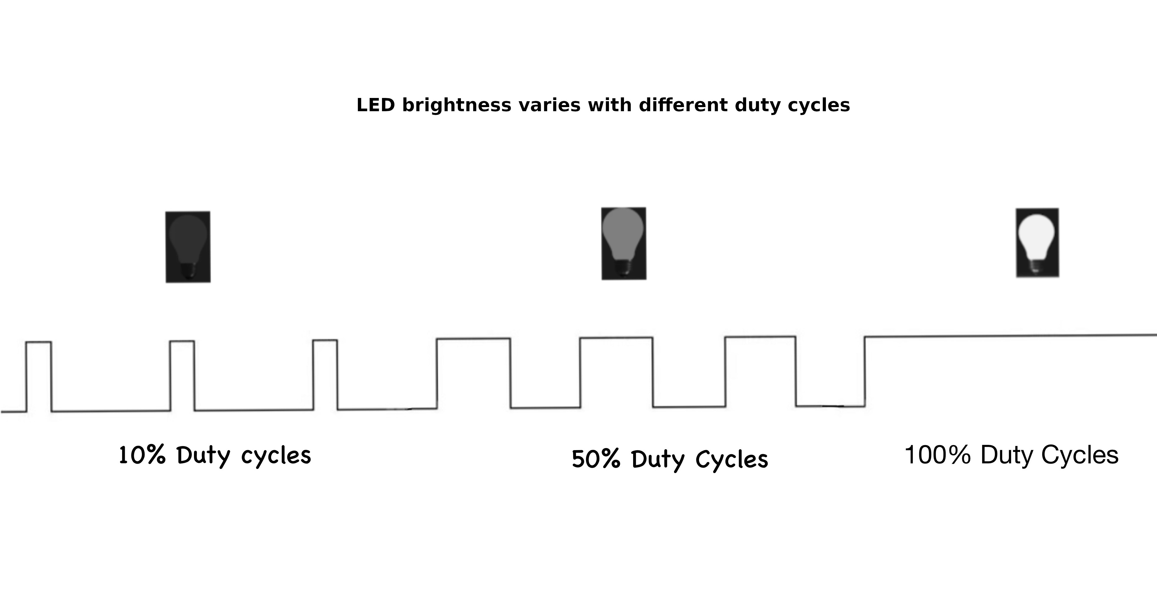
For example:
- A 0 % duty cycle means the signal is always LOW (0 V average).
- A 50 % duty cycle means the signal is HIGH and LOW for equal amounts of time (1.65 V average on a 3.3 V system).
- A 75 % duty cycle means the signal is HIGH for 75 % of the time and LOW for 25 % of the time.
- A 100 % duty cycle means the signal is always HIGH (3.3 V).
Changing the duty cycle changes how much power is delivered to the load, which is why an LED appears dim, medium bright, or fully bright in the image above.
Example Usage 1: Dimming an LED
An LED flashes so quickly that your eyes can’t see individual ON and OFF pulses, so you perceive only the average brightness. A low duty cycle makes it look dim, a higher one makes it look brighter, even though the LED is always switching between full voltage and zero. In the next chapter, we will do this.
Example Usage 2: Controlling a Servo Motor
A servo reads the width of a pulse to decide its angle. It expects a pulse every 20 milliseconds, and the pulse width - about 1 ms for 0°, 1.5 ms for 90°, and 2 ms for 180° - tells the servo where to move.
Period and Frequency
By now, you should have a basic idea of pulse width and duty cycle. Next, we will look at two more important concepts used in PWM: period and frequency.
These two ideas describe how fast the PWM signal repeats.

Period
The period is the total time it takes for one complete ON-OFF cycle to finish. In other words, it is the time from one point in the signal until that same point appears again in the next cycle.
For example:
- In the top part of the diagram, one complete cycle takes 1 second, so the period is 1 second. This is a slow-changing signal.
- In the bottom part of the diagram, one complete cycle takes 0.2 seconds, so the period is 0.2 seconds. This is a faster-changing signal.
Frequency
Frequency tells us how many complete cycles happen in one second. It’s measured in Hertz (Hz).
For example:
- 1 Hz = 1 cycle per second (like the top part of the diagram)
- 5 Hz = 5 cycles per second (like the bottom part of the diagram)
Relationship
The frequency of a signal and its period are inversely related.
\[ \text{Frequency (Hz)} = \frac{1}{\text{Period (s)}} \]
This means:
- When the period gets shorter, the frequency gets higher
- When the period gets longer, the frequency gets lower
Still Confusing? Think of It Like This:
Imagine you and your friend are counting from 0 to 99, over and over again.
You count fast and finish one round quickly. Your friend counts slowly and takes much longer to finish the same round. You both count the same numbers. Only the speed is different.
The time it takes to finish one round is the period. How fast you repeat the rounds is the frequency. Counting faster means a shorter period and a higher frequency. Counting slower means a longer period and a lower frequency.
Examples
So if the period is 1 second, then the frequency will be 1 Hz.
\[ 1 \text{ Hz} = \frac{1 \text{ cycle}}{1 \text{ second}} = \frac{1}{1 \text{ s}} \]
For example, if the period is 20 ms (0.02 s), the frequency will be 50 Hz.
\[ \text{Frequency} = \frac{1}{20 \text{ ms}} = \frac{1}{0.02 \text{ s}} = 50 \text{ Hz} \]
Simulation
Here is the interactive simulation. Use the sliders to adjust the duty cycle and frequency, and watch how the pulse width and LED brightness change. The upper part of the square wave represents when the signal is high (on). The lower part represents when the signal is low (off). The width of the high portion changes with the duty cycle.
If you change the duty cycle from “low to high” and “high to low” in the simulation, you should notice the LED kind of giving a dimming effect.
PWM Peripheral in RP2350
The RP2350 has a PWM peripheral with 12 PWM generators called slices. Each slice contains two output channels (A and B), giving you a total of 24 PWM output channels. For detailed specifications, see page 1077 of the RP2350 Datasheet.
Let’s have a quick look at some of the key concepts.
PWM Generator (Slice)
A slice is the hardware block that generates PWM signals. Each of the 12 slices (PWM0-PWM11) is an independent timing unit with its own 16-bit counter, compare registers, control settings, and clock divider. This independence means you can configure each slice with different frequencies and resolutions.
Channel
Each slice contains two output channels: Channel A and Channel B. Both channels share the same counter, so they run at the same frequency and are synchronized. However, each channel has its own compare register, allowing independent duty cycle control. This lets you generate two related but distinct PWM signals from a single slice.
Mapping of PWM channels to GPIO Pins
Each GPIO pin connects to a specific slice and channel. You’ll find the complete mapping table on page 1078 of the RP2350 Datasheet. For example, GP25 (the onboard LED pin) maps to PWM slice 4, channel B, labeled as 4B.
Initialize the PWM peripheral and get access to all slices:
#![allow(unused)]
fn main() {
let mut pwm_slices = hal::pwm::Slices::new(pac.PWM, &mut pac.RESETS);
}
Get a reference to PWM slice 4 for configuration:
#![allow(unused)]
fn main() {
let pwm = &mut pwm_slices.pwm4;
}
GPIO to PWM
I have created a small form that helps you figure out which GPIO pin maps to which PWM channel and also generates sample code.
Phase-Correct Mode
In standard PWM (fast PWM), the counter counts up from 0 to TOP, then immediately resets to 0. This creates asymmetric edges where the output changes at different points in the cycle.
Phase-correct PWM counts up to TOP, then counts back down to 0, creating a triangular waveform. The output switches symmetrically - once going up and once coming down. This produces centered pulses with edges that mirror each other, reducing electromagnetic interference and creating smoother transitions. The trade-off is that phase-correct mode runs at half the frequency of standard PWM for the same TOP value. See Phase Correct Mode later on for more details on it.
Configure PWM4 to operate in phase-correct mode for smoother output transitions.
Embassy
#![allow(unused)]
fn main() {
let mut pwm_config: Config = Default::default();
pwm_config.phase_correct = true;
let mut pwm_pin = Pwm::new_output_b(p.PWM_SLICE4, p.PIN_25, pwm_config);
}
rp-hal
#![allow(unused)]
fn main() {
pwm.set_ph_correct();
}
Get a mutable reference to channel B of PWM4 and direct its output to GPIO pin 25.
#![allow(unused)]
fn main() {
let channel = &mut pwm.channel_b;
channel.output_to(pins.gpio25);
}
Dimming LED
In this section, we will learn how to create a dimming effect (i.e. reducing and increasing the brightness gradually) for an LED using the Raspberry Pi Pico 2. First, we will dim the onboard LED, which is connected to GPIO pin 25 (based on the datasheet).
To make it dim, we use a technique called PWM (Pulse Width Modulation). You can refer to the intro in the PWM section.
We will gradually increment the PWM’s duty cycle to increase the brightness, then we gradually decrement the PWM duty cycle to reduce the brightness of the LED. This effectively creates the dimming LED effect.
The Eye
“ Come in close… Closer…
Because the more you think you see… The easier it’ll be to fool you…
Because, what is seeing? … You’re looking but what you’re really doing is filtering, interpreting, searching for meaning… “
Here’s the magic: when this switching happens super quickly, our eyes can’t keep up. Instead of seeing the blinking, it just looks like the brightness changes! The longer the LED stays ON, the brighter it seems, and the shorter it’s ON, the dimmer it looks. It’s like tricking your brain into thinking the LED is smoothly dimming or brightening.
Core Logic
What we will do in our program is gradually increase the duty cycle from a low value to a high value in the first loop, with a small delay between each change. This creates the fade-in effect. After that, we run another loop that decreases the duty cycle from high to low, again with a small delay. This creates the fade-out effect.
You can use the onboard LED, or if you want to see the dimming more clearly, use an external LED. Just remember to update the PWM slice and channel to match the GPIO pin you are using.
C 实现
Simulation - LED Dimming with PWM
Here is a simulation to show the dimming effect on an LED based on the duty cycle and the high and low parts of the square wave. I set the default speed very slow so it is clear and not annoying to watch. To start it, click the “Start animation” button. You can increase the speed by reducing the delay time and watching the changes.
LED Dimming on Raspberry Pi Pico with Embassy
Let’s create a dimming LED effect using PWM on the Raspberry Pi Pico with Embassy.
Generate project using cargo-generate
By now you should be familiar with the steps. We use the cargo-generate command with our custom template, and when prompted, select Embassy as the HAL.
cargo generate --git https://github.com/ImplFerris/pico2-template.git --tag v0.3.2
Update Imports
Add the import below to bring the PWM types into scope:
#![allow(unused)]
fn main() {
use embassy_rp::pwm::{Pwm, SetDutyCycle};
}
Initialize PWM
Let’s set up the PWM for the LED. Use the first line for the onboard LED, or uncomment the second one if you want to use an external LED on GPIO 16.
#![allow(unused)]
fn main() {
// For Onboard LED
let mut pwm = Pwm::new_output_b(p.PWM_SLICE4, p.PIN_25, Default::default());

// For external LED connected on GPIO 16
// let mut pwm = Pwm::new_output_a(p.PWM_SLICE0, p.PIN_16, Default::default());
}
Main logic
In the main loop, we create the fade effect by increasing the duty cycle from 0 to 100 percent and then bringing it back down. The small delay between each step makes the dimming smooth. You can adjust the delay and observe how the fade speed changes.
#![allow(unused)]
fn main() {
loop {
    for i in 0..=100 {
        Timer::after_millis(8).await;
        let _ = pwm.set_duty_cycle_percent(i);
    }

    for i in (0..=100).rev() {
        Timer::after_millis(8).await;
        let _ = pwm.set_duty_cycle_percent(i);
    }

    Timer::after_millis(500).await;
}
}
The full code
#![no_std]
#![no_main]

use embassy_executor::Spawner;
use embassy_rp as hal;
use embassy_rp::block::ImageDef;
use embassy_rp::pwm::{Pwm, SetDutyCycle};
use embassy_time::Timer;

//Panic Handler
use panic_probe as _;
// Defmt Logging
use defmt_rtt as _;

/// Tell the Boot ROM about our application
#[unsafe(link_section = ".start_block")]
#[used]
pub static IMAGE_DEF: ImageDef = hal::block::ImageDef::secure_exe();

#[embassy_executor::main]
async fn main(_spawner: Spawner) {
    let p = embassy_rp::init(Default::default());

    // For Onboard LED
    let mut pwm = Pwm::new_output_b(p.PWM_SLICE4, p.PIN_25, Default::default());

    // For external LED connected on GPIO 16
    // let mut pwm = Pwm::new_output_a(p.PWM_SLICE0, p.PIN_16, Default::default());

    loop {
        for i in 0..=100 {
            Timer::after_millis(8).await;
            let _ = pwm.set_duty_cycle_percent(i);
        }
        for i in (0..=100).rev() {
            Timer::after_millis(8).await;
            let _ = pwm.set_duty_cycle_percent(i);
        }
        Timer::after_millis(500).await;
    }
}

// Program metadata for `picotool info`.
// This isn't needed, but it's recomended to have these minimal entries.
#[unsafe(link_section = ".bi_entries")]
#[used]
pub static PICOTOOL_ENTRIES: [embassy_rp::binary_info::EntryAddr; 4] = [
    embassy_rp::binary_info::rp_program_name!(c"led-dimming"),
    embassy_rp::binary_info::rp_program_description!(c"your program description"),
    embassy_rp::binary_info::rp_cargo_version!(),
    embassy_rp::binary_info::rp_program_build_attribute!(),
];

// End of file
Clone the existing project
You can clone the project I created and navigate to the external-led folder:
git clone https://github.com/ImplFerris/pico2-embassy-projects
cd pico2-embassy-projects/led-dimming
Dimming LED Program with RP HAL
rp-hal is an Embedded-HAL for RP series microcontrollers, and can be used as an alternative to the Embassy framework for pico.
This example code is taken from rp235x-hal repo (It also includes additional examples beyond just the blink examples):
“https://github.com/rp-rs/rp-hal/tree/main/rp235x-hal-examples”
The main code
#![no_std]
#![no_main]

use embedded_hal::delay::DelayNs;
use hal::block::ImageDef;
use rp235x_hal as hal;

// Traig for PWM
use embedded_hal::pwm::SetDutyCycle;

//Panic Handler
use panic_probe as _;
// Defmt Logging
use defmt_rtt as _;

/// Tell the Boot ROM about our application
#[unsafe(link_section = ".start_block")]
#[used]
pub static IMAGE_DEF: ImageDef = hal::block::ImageDef::secure_exe();
/// External high-speed crystal on the Raspberry Pi Pico 2 board is 12 MHz.
/// Adjust if your board has a different frequency
const XTAL_FREQ_HZ: u32 = 12_000_000u32;

/// The minimum PWM value (i.e. LED brightness) we want
const LOW: u16 = 0;

/// The maximum PWM value (i.e. LED brightness) we want
const HIGH: u16 = 25000;

#[hal::entry]
fn main() -> ! {
    // Grab our singleton objects
    let mut pac = hal::pac::Peripherals::take().unwrap();

    // Set up the watchdog driver - needed by the clock setup code
    let mut watchdog = hal::Watchdog::new(pac.WATCHDOG);

    // Configure the clocks
    //
    // The default is to generate a 125 MHz system clock
    let clocks = hal::clocks::init_clocks_and_plls(
        XTAL_FREQ_HZ,
        pac.XOSC,
        pac.CLOCKS,
        pac.PLL_SYS,
        pac.PLL_USB,
        &mut pac.RESETS,
        &mut watchdog,
    )
    .ok()
    .unwrap();

    // The single-cycle I/O block controls our GPIO pins
    let sio = hal::Sio::new(pac.SIO);

    // Set the pins up according to their function on this particular board
    let pins = hal::gpio::Pins::new(
        pac.IO_BANK0,
        pac.PADS_BANK0,
        sio.gpio_bank0,
        &mut pac.RESETS,
    );

    // Init PWMs
    let mut pwm_slices = hal::pwm::Slices::new(pac.PWM, &mut pac.RESETS);

    // Configure PWM4
    let pwm = &mut pwm_slices.pwm4;
    pwm.set_ph_correct();
    pwm.enable();

    // Output channel B on PWM4 to GPIO 25
    let channel = &mut pwm.channel_b;
    channel.output_to(pins.gpio25);

    let mut timer = hal::Timer::new_timer0(pac.TIMER0, &mut pac.RESETS, &clocks);

    loop {
        for i in LOW..=HIGH {
            timer.delay_us(8);
            let _ = channel.set_duty_cycle(i);
        }

        for i in (LOW..=HIGH).rev() {
            timer.delay_us(8);
            let _ = channel.set_duty_cycle(i);
        }

        timer.delay_ms(500);
    }
}
// Program metadata for `picotool info`.
// This isn't needed, but it's recomended to have these minimal entries.
#[unsafe(link_section = ".bi_entries")]
#[used]
pub static PICOTOOL_ENTRIES: [hal::binary_info::EntryAddr; 5] = [
    hal::binary_info::rp_cargo_bin_name!(),
    hal::binary_info::rp_cargo_version!(),
    hal::binary_info::rp_program_description!(c"your program description"),
    hal::binary_info::rp_cargo_homepage_url!(),
    hal::binary_info::rp_program_build_attribute!(),
];

// End of file
Clone the existing project
You can clone the blinky project I created and navigate to the led-dimming folder to run this version of the blink program:
git clone https://github.com/ImplFerris/pico2-rp-projects
cd pico2-projects/led-dimming
Buttons
Now that we know how to blink an LED, let’s learn how to read input from a button. This will let us interact with our Raspberry Pi Pico and make our programs respond to what we do.
A button is a small tactile switch. You will find these in most beginner electronic kits. When you press it, the two pins inside make contact and the circuit closes. When you release it, the pins separate and the circuit opens again. Your program can read this open or closed state and do something based on it.
How a Tactile Button Works
A tactile button has four legs arranged in pairs. Looking at the button from above, the legs form a rectangle. The two legs on each side of the button are electrically connected together internally.

I will update this section later with a clearer diagram that shows the internal connections more explicitly. For now, this illustration is enough to understand the concept. The light line indicates that the pins on the left are connected to each other, and the same is true for the pins on the right. When the button is pressed, the left and right sides become connected.
Connecting Buttons to the Pico
Connect one side of the button to Ground and the other side to a GPIO pin (for example, GPIO 15). When the button is pressed, both sides become connected internally, and the GPIO 15 pin gets pulled low. We can check if the pin is pulled low in our code and trigger actions based on it.
Wait. What happens when the button is not pressed? What voltage or level is the GPIO pin reading now? For this to make sense logically, the pin should be in a High state so we can detect the Low state as a button press. But without anything else in the circuit, the GPIO pin will be in something called a floating state. This is unreliable, the pin can randomly switch between High and Low even when no button is pressed. How do we fix this? Let’s see in the next section.
Pull-up and Pull-down Resistors
When working with buttons, switches, and other digital inputs on your Raspberry Pi Pico, you’ll quickly encounter a curious problem: what happens when nothing is connected to an input pin? The answer might surprise you; the pin becomes “floating”, picking up electrical noise and giving you random, unpredictable readings. This is where pull-up and pull-down resistors come to the rescue.
The Floating Pin Problem
Imagine you connect a button directly to a GPIO pin on your Pico. When the button is pressed, it connects the pin to ground (0 V). When released, you might expect the pin to read as HIGH, but it doesn’t work that way. Instead, the pin is disconnected from everything. It’s floating in an undefined state, acting like an antenna that picks up electrical noise from nearby circuits, your hand, or even radio waves in the air.

This floating state will cause your code to read random values, making your button appear to press itself or behave erratically. We need a way to give the pin a default, predictable state.
By the way, you can also connect the button the other way around; connecting one side to 3.3 V instead of ground (though I wouldn’t recommend this for the RP2350, and I’ll explain why shortly). However, you’ll face the same issue. When the button is pressed, it connects to the High state. When released, you might expect it to go Low, but instead it’s in a floating state again.

What Are Pull-up and Pull-down Resistors?
Pull-up and pull-down resistors are simple solutions that ensure a pin always has a known voltage level, even when nothing else is driving it.
Pull-up resistor: Connects the pin to the positive voltage (3.3 V on the Pico) through a resistor. This “pulls” the pin HIGH by default. When you press a button that connects the pin to ground, the pin reads LOW.
Pull-down resistor: Connects the pin to ground (0 V) through a resistor. This “pulls” the pin LOW by default. When you press a button that connects the pin to 3.3 V, the pin reads HIGH.
How Pull-up Resistors Work
Let’s look at a typical button circuit with a pull-up resistor:

When the button is not pressed, current flows through the resistor to the GPIO pin, holding it at 3.3 V (HIGH). When you press the button, you create a direct path to ground. Since electricity follows the path of least resistance, current flows through the button to ground instead of to the pin, and the pin reads LOW.
How Pull-down Resistors Work
A pull-down resistor works in the opposite direction:

When the button is not pressed, the GPIO pin is connected to ground through the resistor, reading LOW. When pressed, the button connects the pin directly to 3.3 V, and the pin reads HIGH.
Internal Pull Resistors
The Raspberry Pi Pico has built-in pull-up and pull-down resistors on every GPIO pin. You don’t need to add external resistors for basic button inputs. You can enable them in software.
Using Pull Resistors in Embedded Rust
Let’s see how to configure internal pull resistors when setting up a button input on the Pico.

As you can see in the diagram, when we enable the internal pull-up resistor, the GPIO pin is pulled to 3.3 V by default. The resistor sits inside the Pico chip itself, so we don’t need any external components; just the button connected between the GPIO pin and ground.
Here’s how to set it up in code:
#![allow(unused)]
fn main() {
let button = Input::new(p.PIN_16, Pull::Up);

// Read the button state
if button.is_low() {
    // Button is pressed (connected to ground)
    // Do something
}
}
With a pull-up resistor enabled, the GPIO pin gets pulled to HIGH voltage by default. When you press the button, it connects the pin to ground, and brings the pin LOW. So the logic is: button not pressed = HIGH, button pressed = LOW.
Setting up a Button with a Pull-down Resistor
Here’s similar code, but this time we use the internal pull-down resistor. With pull-down, the pin is pulled LOW by default. When the button is pressed, connecting the pin to 3.3 V, it reads HIGH.
#![allow(unused)]
fn main() {
let button = Input::new(p.PIN_16, Pull::Down);

// Read the button state
if button.is_high() {
    // Button is pressed (connected to 3.3 V)
    // Do something
}
}
Important
There’s a hardware bug (RP2350-E9) in the initial RP2350 chip released in 2024 that affects internal pull-down resistors.
The bug causes the GPIO pin to read HIGH even when the button isn’t pressed, which is the opposite of what should happen. You can read more about this issue in Simon Monk’s blog post.
The bug was fixed in the newer RP2350 A3 chip revision. If you’re using an older chip, avoid using
Pull::Downin your code. Instead, you can use an external pull-down resistor and setPull::Nonein the code.
With a pull-down resistor enabled, the button should connect to 3.3 V when pressed. The pin reads LOW when not pressed, and HIGH when pressed.
Using a Floating Input
You can also configure a pin without any internal pull resistor:
#![allow(unused)]
fn main() {
let button = Input::new(p.PIN_16, Pull::None);
}
However, as we discussed earlier, floating inputs are unreliable for buttons because they pick up electrical noise and read random values. This option is only useful when you have an external pull-up or pull-down resistor in your circuit, or when connecting to devices that actively drive the pin HIGH or LOW (like some sensors).
C 实现
LED on Button Press
Let’s build a simple project that turns on an LED whenever the button is pressed. You can use an external LED or the built in LED. Just change the LED pin number in the code to match the one you are using.
We will start by creating a new project with cargo generate and our template.
In your terminal, type:
cargo generate --git https://github.com/ImplFerris/pico2-template.git --tag v0.3.2
Button as Input
So far, we’ve been using the Output struct because our Pico was sending signals to the LED. This time, the Pico will receive a signal from the button, so we’ll configure it as an Input.
#![allow(unused)]
fn main() {
let button = Input::new(p.PIN_15, Pull::Up);
}
We’ve connected one side of the button to GPIO 15. The other side is connected to Ground. This means when we press the button, the pin gets pulled to the LOW state. As we discussed earlier, without a pull resistor, the input would be left in a floating state and read unreliable values. So we enable the internal pull-up resistor to keep the pin HIGH by default.
Led as Output
We configure the LED pin as an output, starting in the LOW state (off). If you’re using an external LED, uncomment the first line for GPIO 16. If you’re using the Pico’s built-in LED, use GPIO 25 as shown. Just make sure your circuit matches whichever pin you choose.
#![allow(unused)]
fn main() {
// let mut led = Output::new(p.PIN_16, Level::Low);
let mut led = Output::new(p.PIN_25, Level::Low);
}
Main loop
Now in a loop, we constantly check if the button is pressed by testing whether it’s in the LOW state. We add a small 5-millisecond delay between checks to avoid overwhelming the system. When the button reads LOW (pressed), we set the LED pin HIGH to turn it on, then wait for 3 seconds so we can visually observe it. You can adjust this delay to your preference.
#![allow(unused)]
fn main() {
loop {

    if button.is_low() {
        defmt::info!("Button pressed");
        led.set_high();
        Timer::after_secs(3).await;
    } else {
        led.set_low();
    }

    Timer::after_millis(5).await;

}
}
Note
Debounce: If you reduce the delay, you might notice that sometimes a single button press triggers multiple detections. This is called “button bounce”. When you press a physical button, the metal contacts inside briefly bounce against each other, creating multiple electrical signals in just a few milliseconds. In this example, the 3-second LED delay effectively masks any bounce issues, but in applications where you need to count individual button presses accurately, you’ll need debouncing logic.
We also log “Button pressed” using defmt. If you’re using a debug probe, use the cargo embed --release command to see these logs in your terminal.
The Full code
#![no_std]
#![no_main]

use embassy_executor::Spawner;
use embassy_rp::block::ImageDef;
use embassy_rp::gpio::Pull;
use embassy_rp::{
    self as hal,
    gpio::{Input, Level, Output},
};
use embassy_time::Timer;

//Panic Handler
use panic_probe as _;
// Defmt Logging
use defmt_rtt as _;

/// Tell the Boot ROM about our application
#[unsafe(link_section = ".start_block")]
#[used]
pub static IMAGE_DEF: ImageDef = hal::block::ImageDef::secure_exe();

#[embassy_executor::main]
async fn main(_spawner: Spawner) {
    let p = embassy_rp::init(Default::default());

    let button = Input::new(p.PIN_15, Pull::Up);
    // let mut led = Output::new(p.PIN_16, Level::Low);
    let mut led = Output::new(p.PIN_25, Level::Low);

    loop {
        if button.is_low() {
            defmt::info!("Button pressed");
            led.set_high();
            Timer::after_secs(3).await;
        } else {
            led.set_low();
        }
        Timer::after_millis(5).await;
    }
}

// Program metadata for `picotool info`.
// This isn't needed, but it's recomended to have these minimal entries.
#[unsafe(link_section = ".bi_entries")]
#[used]
pub static PICOTOOL_ENTRIES: [embassy_rp::binary_info::EntryAddr; 4] = [
    embassy_rp::binary_info::rp_program_name!(c"button"),
    embassy_rp::binary_info::rp_program_description!(c"your program description"),
    embassy_rp::binary_info::rp_cargo_version!(),
    embassy_rp::binary_info::rp_program_build_attribute!(),
];

// End of file
Clone the existing project
You can clone (or refer) the project I created and navigate to the button folder.
git clone https://github.com/ImplFerris/pico2-embassy-projects
cd pico2-embassy-projects/button
PWM’s Top and Divider
Sometimes you need to specify a precise frequency for PWM output. For example, hobby servos typically operate at 50 Hz. However, neither embassy-rp nor rp-hal provide a straightforward method to set the frequency directly (at least to my knowledge). Instead, we need to work with the underlying PWM hardware configuration. The embassy-rp crate allows you to configure PWM through a Config struct that has various fields, with our focus being on the top and divider parameters. Let’s explore how these work.
How PWM Works Inside the RP2350
The RP2350’s PWM slice is driven by a clock. This clock is much faster than the PWM signal you actually want on the pin. The PWM hardware uses a counter that repeatedly counts from 0 up to TOP, then wraps back to 0. The TOP register controls how high the counter goes before wrapping.
Each time the counter reaches the top value, it wraps back to zero and starts again. One full count from zero to top is one PWM period.
If the counter increases very quickly, the PWM frequency will be high. If it increases more slowly, the PWM frequency will be lower. This is where the divider comes in.
The RP2350 uses two main 16-bit registers for PWM generation: the Capture/Compare (CC) register and the TOP register. The CC register controls how long the output pulse stays high within each cycle (the duty cycle). The TOP register controls how long each complete cycle takes (the period).

For simple explanation, let’s say the TOP value is 9 and CC value is 3. It will count from 0 to 9 as illustrated in the digram. The signal stay high until it reaches CC value. After that, it remains low in that cycle. Take your own time and try to understand the above diagram. In the diagram, each count, we have drawn as steps (red colored). The pulse stays in high (colored in green) until the count matches CC value. As you can see, after 3 till 9, the pulse becomes low.
How TOP Controls Frequency
The PWM counter counts from 0 up to the TOP value, then wraps back to 0. One complete count cycle (0 to TOP) produces one PWM period. The frequency is simply how many of these complete cycles happen per second.
The system clock of the RP2350 runs at 150 MHz (150 million cycles per second). If we ignore the divider for now and keep it at 1, the counter increments once per system clock cycle. Understanding how TOP affects frequency is crucial:
- Higher TOP value => Counter takes more steps to complete one cycle => Lower PWM frequency
- Lower TOP value => Counter takes fewer steps to complete one cycle => Higher PWM frequency
Let’s look at some concrete examples to make this clear:
Example 1: TOP = 149
The counter counts: 0, 1, 2, 3, … 148, 149, then wraps to 0.
That’s 150 total counts per cycle (counting from 0 through 149 inclusive).
At 150 MHz system clock, the PWM frequency is:
Note
Don’t rely on this simplified formula yet. It’s not accurate enough because there’s one more factor to add (the clock divider). We’re showing it here just to understand the basic TOP-frequency relationship.
\[ f_{PWM} = \frac{150,000,000}{150} = 1,000,000 \text{ Hz (1 MHz)} \]
Example 2: TOP = 1,499
The counter counts through 1,500 values (0 through 1,499)
PWM frequency:
\[ f_{PWM} = \frac{150,000,000}{1,500} = 100,000 \text{ Hz (100 kHz)} \]
Why TOP Alone Is Not Enough
The TOP register is 16 bits wide, so the maximum value it can hold is 65,535. This means the counter goes through 65,536 steps before wrapping back to zero. If we apply this maximum TOP value to the same calculation we used in the examples above, the resulting PWM frequency comes out to about 2,288 Hz.
That is the lowest frequency we can reach using TOP alone with the system clock running at 150 MHz.
This is still far too high for many real-world uses. For example, hobby servo motors require a PWM frequency of around 50 Hz. With TOP alone, there is simply no way to slow the PWM down enough to reach that range.
To solve this, the RP2350 provides an additional control: the PWM clock divider. By dividing down the clock that feeds the PWM counter, we can generate much lower frequencies, including the 50 Hz required by servos.
The Clock Divider
The clock divider slows down the clock that drives the PWM counter. Instead of counting at the full 150 MHz system clock speed, the counter increments more slowly based on the divider value.
When the divider is increased, each count takes longer. This means the counter needs more time to go from 0 to TOP, so the PWM frequency becomes lower. This is what allows us to reach low frequencies like 50 Hz, which are impossible using TOP alone.
Let’s look at one more simplified example before introducing the actual formula from the RP2350’s datasheet.
Suppose we set TOP to 1,499, so the counter goes through 1,500 steps (0 through 1,499). Now, if we set the clock divider to 10, each step takes 10 system clock cycles instead of 1.
\[ f_{PWM} = \frac{150{,}000{,}000}{1{,}500 \times 10} = 10{,}000\ \text{Hz (10 kHz)} \]
Without the divider, we got 100 kHz for the same TOP value. Now with a divider of 10, we get 10 kHz; ten times slower. This shows how the divider gives us control over slowing down the PWM frequency.
Phase Correct Mode
Bear with me for a moment. Before introducing the actual formula, there is one more important concept we need to understand.
So far, we have assumed that the PWM counter counts in one direction, from 0 up to TOP, and then immediately wraps back to 0. This is not the only way PWM can work. In phase correct mode, the counter behaves differently, and that has a direct effect on the PWM frequency.
In phase correct mode, the PWM counter does not jump back to zero when it reaches TOP. Instead, it counts up from 0 to TOP, then counts back down from TOP to 0. This creates a symmetric, up-and-down counting pattern.
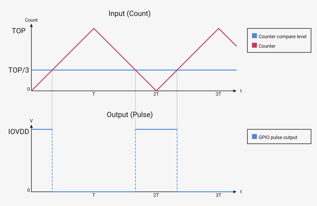
Because of this, one full PWM cycle now includes both the upward count and the downward count. In other words, the counter takes roughly twice as long to complete a full cycle compared to the normal up-counting mode.
The important takeaway is simple: enabling phase correct mode halves the PWM frequency for the same TOP and divider values.
This mode is often used when you want cleaner, more symmetric PWM signals, especially for things like motor control.
The PWM Frequency Formula
The RP2350 datasheet defines exactly how the PWM period is calculated. The period tells you how many system clock cycles are needed for one full PWM cycle.
Calculate the period in clock cycles with the following equation:
\[ \text{period} = (\text{TOP} + 1) \times (\text{CSR_PH_CORRECT} + 1) \times \left( \text{DIV_INT} + \frac{\text{DIV_FRAC}}{16} \right) \]
To determine the output frequency based on the system clock frequency, use the following equation:
\[ f_{PWM} = \frac{f_{sys}}{\text{period}} = \frac{f_{sys}}{(\text{TOP} + 1) \times (\text{CSR_PH_CORRECT} + 1) \times \left( \text{DIV_INT} + \frac{\text{DIV_FRAC}}{16} \right)} \]
Where:
- \( f_{PWM} \) is the PWM output frequency.
- \( f_{sys} \) is the system clock frequency. For the Pico 2, it is is 150 MHz.
Divider and Fraction
In the formula we discussed earlier, there is one important part we have not explained yet: DIV_FRAC. This controls the fractional part of the clock divider in the RP2350.
The RP2350 clock divider is split into two parts. DIV_INT is the integer part and sets the whole number division. DIV_FRAC is the fractional part and allows finer control over the division ratio. Together, they let you slow down the PWM counter more precisely than using an integer divider alone. One important rule is that when DIV_INT is set to 0, you must not set any DIV_FRAC bits.
Manually Calculate Top
In this section, we will manually derive the TOP value for a given PWM frequency. This method requires trying different divider values and checking whether the resulting TOP value falls within the valid range.
There is a better approach in the next section, where you can use either Rust code or a calculator form to compute both TOP and the divider automatically. For now, this manual method is useful because it helps build intuition about how the clock, divider, and TOP value relate to each other.
The TOP value must be within the range 0 to 65534. Although TOP is stored in a 16-bit unsigned register, setting it to 65535 prevents achieving a true 100 percent duty cycle. This is because the duty cycle compare register (CC) must be set to TOP + 1 to achieve a true 100 percent duty cycle, and CC itself is also only 16 bits wide. By keeping TOP at or below 65534, the value TOP + 1 still fits in the CC register, allowing the full 0 to 100 percent duty cycle range to be represented correctly.
To ensure TOP stays within this limit, we will choose divider values that are powers of two, such as 8, 16, 32, or 64. This approach does not work for every possible frequency. In some cases, you may need other integer values or even fractional dividers. To keep things simple, we will start with this approach.
As an example, we will calculate the values required to generate a 50 Hz PWM signal for a servo motor.
PWM Frequency Formula
The RP2350 datasheet defines the PWM frequency as:
\[ f_{PWM} = \frac{f_{sys}}{\text{period}} = \frac{f_{sys}}{(\text{TOP} + 1) \times (\text{CSR_PH_CORRECT} + 1) \times \left( \text{DIV_INT} + \frac{\text{DIV_FRAC}}{16} \right)} \]
Here’s the derived formula to get the TOP for the target frequency:
\[ \text{TOP} = \frac{f_{sys}} {f_{PWM} \times (\text{CSR_PH_CORRECT} + 1) \times \left( \text{DIV_INT} + \frac{\text{DIV_FRAC}}{16} \right)} - 1 \]
Where:
- \( f_{PWM} \) is the desired PWM frequency.
- \( f_{sys} \) is the system clock frequency. For the Pico 2, it is is 150 MHz.
We’re not going to use phase correct mode and we’re not using fraction for the divider either, so let’s simplify the formula further:
\[ \text{TOP} = \frac{f_{sys}} {f_{PWM} \times \text{DIV_INT}} - 1 \]
TOP for 50 Hz
We want the PWM frequency to be 50 Hz. To achieve that, we substitute the system clock frequency, target frequency and the chosen divider integer, and we get the following TOP value:
\[ \text{top} = \frac{150,000,000}{50 \times 64} - 1 \]
\[ \text{top} = \frac{150,000,000}{3,200} - 1 \]
\[ \text{top} = 46,875 - 1 \]
\[ \text{top} = 46,874 \]
You can experiment with different divider values (even including fraction) and corresponding top values.
TOP and Divider Finder for the Target Frequency
In MicroPython, you can set the PWM frequency directly without manually calculating the TOP and divider values. Internally, MicroPython computes these values from the target frequency and the system clock.
I wanted to see if there was something similar available in Rust. While discussing this in the rp-rs Matrix chat, 9names ported the relevant C code from MicroPython that calculates TOP and divider values into Rust. This code takes the target frequency and source clock frequency as input and gives us the corresponding TOP and divider values. You can find that implementation here.
You can use that Rust code directly in your own project. I compiled the same code to WASM and built a small form around it so that you can try it out here.
By default, the source clock frequency is set to the RP2350 system clock frequency of 150 MHz, and the target frequency is set to 50 Hz. You can change both values if needed.
TOP and divider calculation
Result
Note
The divider is shown as an integer part and a fractional part.
The fractional value is not a decimal fraction. It represents a 4-bit fixed-point fraction.
The effective divider is:
DIV = DIV_INT + (DIV_FRAC / 16)For example,
DIV_INT = 45andDIV_FRAC = 13means the divider is45 + 0.8125, not45.13.
Code
If you are using rp-hal, you set the integer and fractional parts separately, like this:
#![allow(unused)]
fn main() {
pwm.set_top(65483);
pwm.set_div_int(45);
pwm.set_div_frac(13);
}
If you are using embassy-rp, both parts are combined into a single divider field inside the Config struct. Nope, this is not a floating-point value. Internally, it uses a fixed-point number to represent the integer and fractional parts together. If you are not familiar with fixed-point numbers, I have a separate blog post explaining them in detail, which you can read here.
If you only need an integer divider, you can simply convert a u8 value:
#![allow(unused)]
fn main() {
let mut servo_config: PwmConfig = Default::default();
servo_config.top = 46_874;
servo_config.divider = 64.into();
}
If you also want a fractional part, you need to add the fixed crate as a dependency and construct the divider using a fixed-point type:
#![allow(unused)]
fn main() {
let mut servo_config: PwmConfig = Default::default();
servo_config.top = 65483;
servo_config.divider = FixedU16::<U4>::from_num(45.8125);
// or
// servo_config.divider = fixed::types::U12F4::from_num(45.8125);
}
Servo Motors
Servo motors let you control position accurately. You might use them to point a camera, move parts of a small robot, or control switches automatically. They’re different from regular DC motors. Instead of spinning continuously, a servo moves to a specific angle and stays there.
In this chapter, we’ll make a servo sweep through three positions: 0°, 90°, and 180°.
Hardware Used
For this chapter, we will use the following components:
- SG90 Micro Servo Motor
- Jumper Wires:
- Female-to-Male (or Male to Male depending on how you are connecting) jumper wires for connecting the Pico 2 to the servo motor pins (Ground, Power, and Signal).
The SG90 is small, cheap, and easy to find. It is commonly used in learning projects and works well for demonstrations.
Servo Motor Basics
A typical hobby servo has three wires: Ground, Power, Signal. The power and ground wires supply energy to the motor. The signal wire is used to tell the servo which position to move to. The servo expects a PWM signal on this pin. Different pulse widths correspond to different angles.

You do not need to know the internal details to use a servo. You just need to generate the correct PWM signal.
How Servo Control Works
A servo motor uses PWM (Pulse Width Modulation) signals to control its position. The width of each pulse tells the servo which angle to move to, and continuously repeating that pulse keeps it there.
Basic Operation
Servos operate on a 50 Hz frequency, meaning they expect a control pulse every 20 milliseconds. Within each 20 ms cycle, the duration that the signal stays high determines the servo’s position.
Think of it like this: every 20 ms, you send the servo a brief instruction. That instruction’s length tells the servo where to point.
Pulse Width
The position of the servo is controlled by how long the signal pulse stays high. A short pulse moves it to the minimum position (typically 0°), a medium pulse moves it to center (typically 90°), and a long pulse moves it to the maximum position (typically 180°).
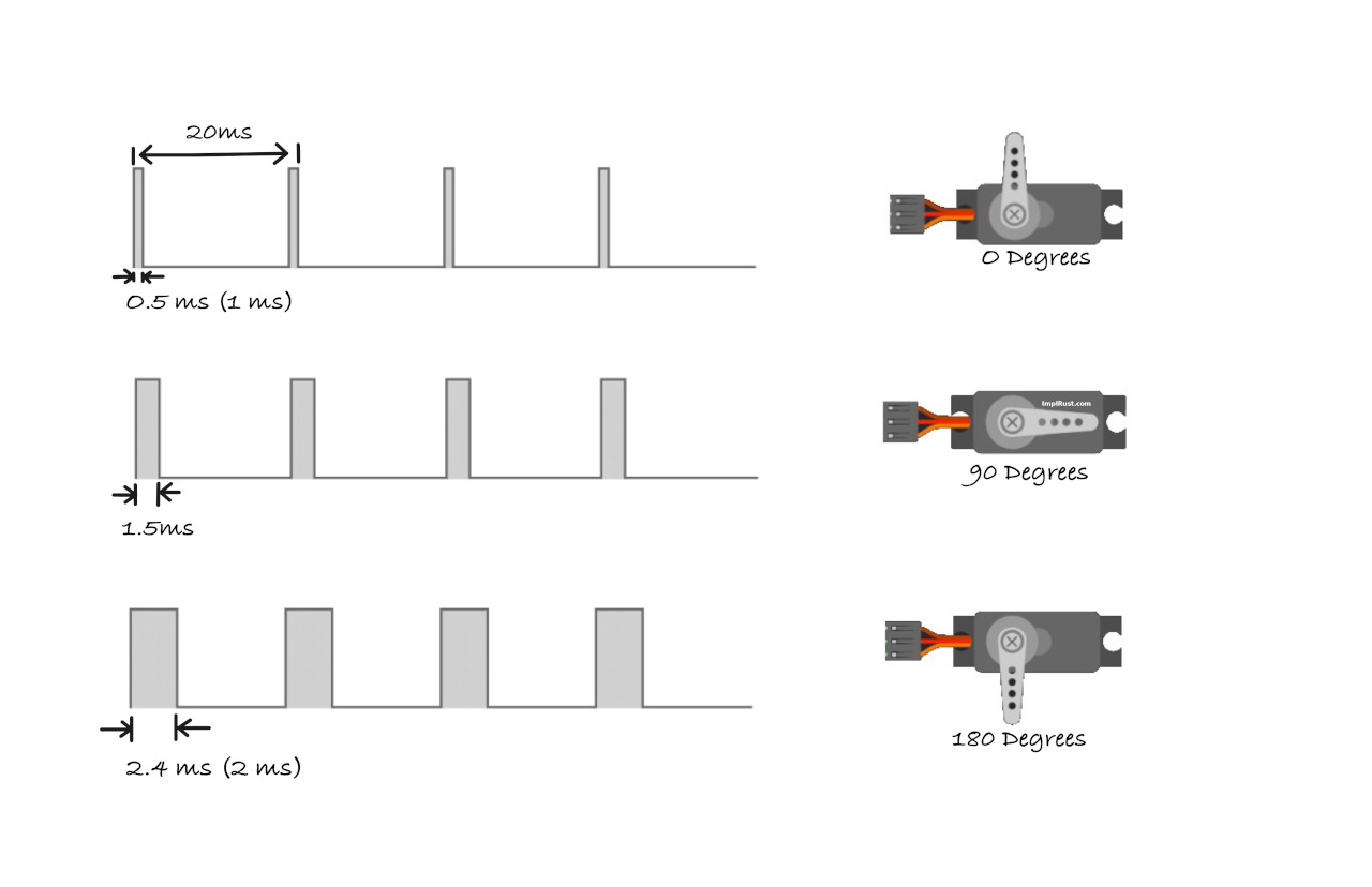
Standard vs. Reality
You’ll often see these “standard” values referenced: 1.0 ms pulse for 0°, 1.5 ms pulse for 90°, and 2.0 ms pulse for 180°. However, cheap servos rarely follow these numbers exactly. Manufacturing variations mean each servo has its own characteristics.
For example, my servo required 0.5 ms for minimum position, 1.5 ms for center, and 2.4 ms for maximum position. This is completely normal and expected.
Treat published pulse widths as starting points, not absolute values. Always test and calibrate your specific servo. A logic analyzer or oscilloscope helps, but simple trial and error works fine too. The examples in this guide use values that worked for my servo, so you may need to adjust them for yours.
Calculating Duty Cycle
The duty cycle represents the percentage of time the signal stays high during each 20 ms cycle. Understanding this helps you configure PWM correctly in your code.
Example Calculations
For a 0.5 ms pulse (0° position), the duty cycle is calculated as:
A 0.5 ms pulse means the signal is “high” for 0.5 milliseconds within each 20 ms cycle. The servo interprets this as a command to move to the 0-degree position.
\[ \text{Duty Cycle (%)} = \frac{0.5 \text{ms}}{20 \text{ms}} \times 100 = 2.5\% \]
This means that for just 2.5 % of each 20 ms cycle, the signal stays “high” causing the servo to rotate to the 0-degree position.
For a 1.5 ms pulse (90° position), the calculation gives us:
A 1.5 ms pulse means the signal is “high” for 1.5 milliseconds in the 20 ms cycle. The servo moves to its neutral position, around 90 degrees (middle position).
\[ \text{Duty Cycle (%)} = \frac{1.5 \text{ms}}{20 \text{ms}} \times 100 = 7.5\% \]
Here, the signal stays “high” for 7.5 % of the cycle, which positions the servo at 90 degrees (neutral).
For a 2.4 ms pulse (180° position), we get:
A 2.4 ms pulse means the signal is “high” for 2.4 milliseconds in the 20 ms cycle. The servo will move to its maximum position, typically 180 degrees (full rotation to one side).
\[ \text{Duty Cycle (%)} = \frac{2.4 \text{ms}}{20 \text{ms}} \times 100 = 12\% \]
In this case, the signal is “high” for 12% of the cycle, which causes the servo to rotate to 180 degrees.
Reference
Servo with Raspberry Pi Pico 2 (RP2350)
The required power supply and pulse width can vary depending on the servo motor you use, so it is always best to check the datasheet or product specifications. The servo I am using operates in the 4.8 V to 6 V range, so I will power it with 5 V.
- Ground (GND): Connect the servo’s GND pin (typically the brown wire, though it may vary) to any ground pin on the Pico 2.
- Power (VCC): Connect the servo’s VCC pin (usually the red wire) to the Pico 2’s 5 V power pin(VBUS).
- Signal (PWM): Connect the servo’s control (signal) pin to GPIO15 on the Pico 2, configured for PWM. This is commonly the orange wire (may vary).
| Pico Pin | Wire | Servo Motor | Notes |
|---|---|---|---|
| VBUS |
|
Power (Red Wire) | Supplies 5 V power to the servo. |
| GND |
|
Ground (Brown Wire) | Connects to ground. |
| GPIO 15 |
|
Signal (Orange/yellow Wire) | Receives PWM signal to control the servo's position. |
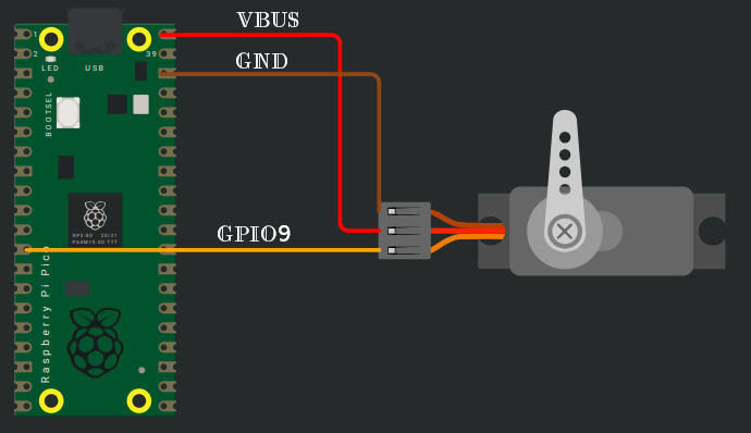
角度与占空比
Position and Duty Cycle
To control a servo with the Raspberry Pi Pico, we need to set a 50 Hz PWM frequency. There is no straightforward way to set the frequency directly in embassy or rp-hal, at least to my knowledge.
In embassy-rp, PWM is configured using a Config struct with multiple fields. For our use case, we mainly care about the top and divider values. The same applies to rp-hal, where we can set top, div_int, and div_frac separately.
You can either use the manual method to find a suitable TOP value, or use the form to automatically calculate both TOP and the divider for the target frequency of 50 Hz.
Using the manual method, I calculated a TOP value of 46,874 with a divider of 64. Using the form, I got a divider of 45.8125 with a TOP value of 65,483. We can use either of these configurations.
Note
In rp-hal, you have to set the divider integer and fraction separately. So a divider of 64 becomes div_int = 64 and div_frac = 0. A divider of 45.8125 becomes div_int = 45 and div_frac = 13.
Position calculation based on top
Once the TOP value for a 50 Hz PWM signal is known, we can calculate the duty cycle values required to position the servo.
The servo determines its position by measuring the pulse width, which is the amount of time the signal stays high during each 20 ms PWM cycle. The exact pulse widths are not identical for all servos and can vary slightly depending on the specific servo model.
In my case, the values were:
-
0° at about 0.5 ms, which corresponds to a 2.5 % duty cycle since 0.5 ms is 2.5 % of a 20 ms period.
-
90° at about 1.5 ms, which corresponds to a 7.5 % duty cycle since 1.5 ms is 7.5 % of a 20 ms period.
-
180° at about 2.4 ms, which corresponds to a 12 % duty cycle since 2.4 ms is 12 % of a 20 ms period.
In the LED dimming chapter, changing the duty cycle was straightforward. We only cared about brightness, not frequency, so using set_duty_cycle_percent was sufficient. That function accepts a u8 value from 0 to 100, which works well for whole-number percentages.
For servo control, this approach is not suitable because the required duty cycles include fractional values such as 2.5%, 7.5%, and 12%.
We therefore have two alternatives. One option is to calculate the duty value directly from TOP and use set_duty_cycle, which accepts a u16. The other option is to use set_duty_cycle_fraction, which lets you specify the duty cycle as a numerator and denominator.
Option 1: Manual calculation with set_duty_cycle
We first convert the pulse width into a percentage of the period. That percentage is then multiplied by TOP + 1 to obtain the duty value that configures the PWM output.
#![allow(unused)]
fn main() {
const PWM_DIV_INT: u8 = 64;
const PWM_TOP: u16 = 46_874;

const TOP: u16 = PWM_TOP + 1;
// 0.5ms is 2.5% of 20ms; 0 degrees in servo
const MIN_DUTY: u16 = (TOP as f64 * (2.5 / 100.)) as u16;
// 1.5ms is 7.5% of 20ms; 90 degrees in servo
const HALF_DUTY: u16 = (TOP as f64 * (7.5 / 100.)) as u16;
// 2.4ms is 12% of 20ms; 180 degree in servo
const MAX_DUTY: u16 = (TOP as f64 * (12. / 100.)) as u16;
}
Once the duty value is calculated, it can be applied like this:
#![allow(unused)]
fn main() {
servo.set_duty_cycle(MIN_DUTY)
            .expect("invalid min duty cycle");
}
Option 2: Using set_duty_cycle_fraction
Another option is to use set_duty_cycle_fraction. This will help us to set percentage with fraction.
In fact, set_duty_cycle_percent is a convenience method provided by embedded-hal that internally calls set_duty_cycle_fraction. It simply divides the input percentage by 100 and forwards the result as a fraction.
From embedded-hal:
#![allow(unused)]
fn main() {
/// Set the duty cycle to `percent / 100`
///
/// The caller is responsible for ensuring that `percent` is less than or equal to 100.
#[inline]
fn set_duty_cycle_percent(&mut self, percent: u8) -> Result<(), Self::Error> {
    self.set_duty_cycle_fraction(u16::from(percent), 100)
}

/// Set the duty cycle to `num / denom`.
///
/// The caller is responsible for ensuring that `num` is less than or equal to `denom`,
/// and that `denom` is not zero.
fn set_duty_cycle_fraction(&mut self, num: u16, denom: u16) -> Result<(), Self::Error> {
    debug_assert!(denom != 0);
    debug_assert!(num <= denom);
    let duty = u32::from(num) * u32::from(self.max_duty_cycle()) / u32::from(denom);

    // This is safe because we know that `num <= denom`, so `duty <= self.max_duty_cycle()` (u16)
    #[allow(clippy::cast_possible_truncation)]
    {
        self.set_duty_cycle(duty as u16)
    }
}
}
This function does not accept floating-point values. Instead, it takes a numerator and a denominator, both as u16. To represent fractional percentages, we simply scale them into integers.
Remember that 2.5 % can be written as the fraction 2.5/100. Since we can’t use decimals in the numerator, we multiply both the numerator and denominator by 10 to get equivalent integer fractions:
#![allow(unused)]
fn main() {
2.5/100 = (2.5 × 10)/(100 × 10) = 25/1000
}
Now we have an equivalent fraction using only integers. We can apply the same conversion to our other percentages:
For example:
- 2.5% can be written as 25 / 1000 (in other words, 25 is 2.5 % of 1000)
- 7.5% can be written as 75 / 1000 (in other words, 75 is 7.5 % of 1000)
- 12% can be written as 120 / 1000 (in other words, 120 is 12 % of 1000)
So in our code, we can apply it like this:
#![allow(unused)]
fn main() {
// Move servo to 0° position (2.5 % duty cycle = 25/1000)
servo.set_duty_cycle_fraction(25, 1000)
    .expect("invalid duty cycle");

// 90° position (7.5 % duty cycle)
servo.set_duty_cycle_fraction(75, 1000)
    .expect("invalid duty cycle");

// 180° position (12 % duty cycle)
servo.set_duty_cycle_fraction(120, 1000)
    .expect("invalid duty cycle");
}
C 实现
Servo Motor Control on Raspberry Pi Pico Using Embassy and Rust
In this section, we will create a simple program that moves the servo horn from 0 to 90 to 180 and then back to 0. This basic movement is enough to understand how PWM controls a servo. Once you are comfortable with the idea, you can experiment further and build more interesting applications.
We will start by creating a new project using the Embassy framework. After that, we wll build the same project again using rp-hal. As usual, generate the project from the template with cargo-generate:
cargo generate --git https://github.com/ImplFerris/pico2-template.git --tag v0.3.2
When prompted, give your project a name like “servo-motor” and choose “embassy” as the HAL. Enable defmt logging, if you have a debug probe so you can view logs also.
Additional Imports
In addition to the usual boilerplate imports, you’ll need to add these specific imports to your project.
#![allow(unused)]
fn main() {
// For PWM
use embassy_rp::pwm::{Config as PwmConfig, Pwm, SetDutyCycle};
}
PWM Config
In the LED dimming chapter, we left the PWM configuration at its default values. That was sufficient there, because only the duty cycle mattered.
This time, we cannot do that. For servo control, we have to configure the TOP value and the divider ourselves so that the PWM frequency comes out to 50 Hz, based on the values we calculated earlier.
Here, I am using the manually calculated TOP and divider values directly in the code instead of using the calculator form. The divider I am using is a whole number, so I can simply convert it using the into() method. If the divider had a fractional part, I would need to use the fixed crate, which we already looked at earlier. To keep things simple, I am sticking to the integer version for now.
#![allow(unused)]
fn main() {
const PWM_DIV_INT: u8 = 64;
const PWM_TOP: u16 = 46_874;
}
Note
You can also try this with a fractional divider. We already looked at the code snippet for that earlier, so you can reuse it and experiment with fractional values if you want.
Once we have those values, we just apply them to the PWM configuration like this.
#![allow(unused)]
fn main() {
let mut servo_config: PwmConfig = Default::default();
servo_config.top = PWM_TOP;
servo_config.divider = PWM_DIV_INT.into();
}
Initialize PWM
Once the PWM configuration is ready, the next step is to create a PWM output and bind it to the GPIO pin connected to the servo signal wire.
In our case, we are using the GPIO 15. Feel free to change these if your wiring is different.
#![allow(unused)]
fn main() {
let mut servo = Pwm::new_output_b(p.PWM_SLICE7, p.PIN_15, servo_config);
}
Main loop
Now we move on to the main loop. Here, we simply change the duty cycle value, wait for a short delay, and then move to the next position.
#![allow(unused)]
fn main() {
loop {
    // Move servo to 0° position (2.5 % duty cycle = 25/1000)
    servo
        .set_duty_cycle_fraction(25, 1000)
        .expect("invalid min duty cycle");

    Timer::after_millis(1000).await;

    // 90° position (7.5 % duty cycle)
    servo
        .set_duty_cycle_fraction(75, 1000)
        .expect("invalid half duty cycle");

    Timer::after_millis(1000).await;

    // 180° position (12 % duty cycle)
    servo
        .set_duty_cycle_fraction(120, 1000)
        .expect("invalid max duty cycle");

    Timer::after_millis(1000).await;
}
}
If everything works, you should see the servo horn move to the first position, pause briefly, move to the next position, and then move to the final position before returning back again.
Clone the existing project
You can clone (or refer) project I created and navigate to the servo-motor folder.
git clone https://github.com/ImplFerris/pico2-embassy-projects
cd pico2-embassy-projects/servo-motor
Debugging
If your servo is not moving, start by checking the wiring. Make sure the signal wire is connected to the correct GPIO pin, the servo has a proper power source, and the ground is shared with the Pico.
Next, double check that the code was flashed correctly and that the program is actually running on the board. If you are using a debug probe with defmt enabled, the log output can help confirm this.
If everything looks correct and the servo still does not move as expected, the most likely reason is that your servo uses slightly different pulse widths for each position. In that case, refer to the datasheet for your specific servo model, or check the manufacturer or vendor website if they provide timing information. You may need to adjust the duty cycle values to match your servo.
Do not worry if this does not work perfectly the first time. This is one of the things I struggled with when I started as well. I have tried my best to explain the calculations and the reasoning behind them clearly. I hope this helps.
The Full Code
#![no_std]
#![no_main]

use embassy_executor::Spawner;
use embassy_rp as hal;
use embassy_rp::block::ImageDef;
use embassy_time::Timer;

//Panic Handler
use panic_probe as _;
// Defmt Logging
use defmt_rtt as _;

// PWM
use embassy_rp::pwm::{Config as PwmConfig, Pwm, SetDutyCycle};

/// Tell the Boot ROM about our application
#[unsafe(link_section = ".start_block")]
#[used]
pub static IMAGE_DEF: ImageDef = hal::block::ImageDef::secure_exe();

const PWM_DIV_INT: u8 = 64;
const PWM_TOP: u16 = 46_874;

// Alternative method:
// const TOP: u16 = PWM_TOP + 1;
// const MIN_DUTY: u16 = (TOP as f64 * (2.5 / 100.)) as u16;
// const HALF_DUTY: u16 = (TOP as f64 * (7.5 / 100.)) as u16;
// const MAX_DUTY: u16 = (TOP as f64 * (12. / 100.)) as u16;

#[embassy_executor::main]
async fn main(_spawner: Spawner) {
    let p = embassy_rp::init(Default::default());

    let mut servo_config: PwmConfig = Default::default();
    servo_config.top = PWM_TOP;
    servo_config.divider = PWM_DIV_INT.into();

    let mut servo = Pwm::new_output_b(p.PWM_SLICE7, p.PIN_15, servo_config);

    loop {
        // Move servo to 0° position (2.5 % duty cycle = 25/1000)
        servo
            .set_duty_cycle_fraction(25, 1000)
            .expect("invalid min duty cycle");
        Timer::after_millis(1000).await;

        // 90° position (7.5 % duty cycle)
        servo
            .set_duty_cycle_fraction(75, 1000)
            .expect("invalid half duty cycle");
        Timer::after_millis(1000).await;

        // 180° position (12 % duty cycle)
        servo
            .set_duty_cycle_fraction(120, 1000)
            .expect("invalid max duty cycle");
        Timer::after_millis(1000).await;
    }

    // Alternative method
    // loop {
    //     servo
    //         .set_duty_cycle(MIN_DUTY)
    //         .expect("invalid min duty cycle");
    //     Timer::after_millis(1000).await;

    //     servo
    //         .set_duty_cycle(HALF_DUTY)
    //         .expect("invalid half duty cycle");
    //     Timer::after_millis(1000).await;

    //     servo
    //         .set_duty_cycle(MAX_DUTY)
    //         .expect("invalid max duty cycle");
    //     Timer::after_millis(1000).await;
    // }
}

// Program metadata for `picotool info`.
// This isn't needed, but it's recomended to have these minimal entries.
#[unsafe(link_section = ".bi_entries")]
#[used]
pub static PICOTOOL_ENTRIES: [embassy_rp::binary_info::EntryAddr; 4] = [
    embassy_rp::binary_info::rp_program_name!(c"servo-motor"),
    embassy_rp::binary_info::rp_program_description!(c"your program description"),
    embassy_rp::binary_info::rp_cargo_version!(),
    embassy_rp::binary_info::rp_program_build_attribute!(),
];

// End of file
Servo Motor Control on Raspberry Pi Pico Using rp-hal
In this exercise, we repeat the same servo control example, but this time using rp hal instead of Embassy. The overall idea stays exactly the same. The main difference here is that we will use a fractional divider instead of a whole number divider.
For this, we will rely on the calculator form to generate the TOP value and both the integer and fractional parts of the divider.
cargo generate --git https://github.com/ImplFerris/pico2-template.git --tag v0.3.2
When prompted, give your project a name like “servo-motor” and choose “rp-hal” as the HAL. Enable defmt logging, if you have a debug probe so you can view logs also.
Additional Imports
Along with the usual rp hal boilerplate, we need to bring in the trait that allows us to update the PWM duty cycle.
#![allow(unused)]
fn main() {
// For PWM
use embedded_hal::pwm::SetDutyCycle;
}
Initialize PWM Slice
Next, we initialize the PWM peripheral and select the slice we want to use. In our case, we are using PWM slice 7 (since we are using GPIO 15).
#![allow(unused)]
fn main() {
let mut pwm_slices = hal::pwm::Slices::new(pac.PWM, &mut pac.RESETS);
let pwm = &mut pwm_slices.pwm7;
}
Configure Divider and TOP
Now we apply the TOP value and the divider that were generated using the calculator form. This time, we explicitly set both the integer and fractional parts of the divider.
#![allow(unused)]
fn main() {
pwm.set_div_int(45);
pwm.set_div_frac(13);
pwm.set_top(65483);
pwm.enable();
}
Attach PWM Channel to GPIO
#![allow(unused)]
fn main() {
let servo = &mut pwm.channel_b;
servo.output_to(pins.gpio15);
}
Main Loop
Finally, inside the main loop, we update the duty cycle to move the servo between different positions. Just like in the Embassy example, we use set_duty_cycle_fraction.
#![allow(unused)]
fn main() {
loop {
    // Move servo to 0° position (2.5 % duty cycle = 25/1000)
    servo
        .set_duty_cycle_fraction(25, 1000)
        .expect("invalid min duty cycle");
    timer.delay_ms(1000);

    // 90° position (7.5 % duty cycle)
    servo
        .set_duty_cycle_fraction(75, 1000)
        .expect("invalid half duty cycle");
    timer.delay_ms(1000);

    // 180° position (12 % duty cycle)
    servo
        .set_duty_cycle_fraction(120, 1000)
        .expect("invalid max duty cycle");
    timer.delay_ms(1000);
}
}
Clone the existing project
You can clone (or refer) project I created and navigate to the servo-motor folder.
git clone https://github.com/ImplFerris/pico2-rp-projects
cd pico2-projects/servo-motor
The Full Code
#![no_std]
#![no_main]

use embedded_hal::delay::DelayNs;
use hal::block::ImageDef;
use rp235x_hal as hal;

use embedded_hal::pwm::SetDutyCycle;

//Panic Handler
use panic_probe as _;
// Defmt Logging
use defmt_rtt as _;

/// Tell the Boot ROM about our application
#[unsafe(link_section = ".start_block")]
#[used]
pub static IMAGE_DEF: ImageDef = hal::block::ImageDef::secure_exe();
/// External high-speed crystal on the Raspberry Pi Pico 2 board is 12 MHz.
/// Adjust if your board has a different frequency
const XTAL_FREQ_HZ: u32 = 12_000_000u32;

#[hal::entry]
fn main() -> ! {
    // Grab our singleton objects
    let mut pac = hal::pac::Peripherals::take().unwrap();

    // Set up the watchdog driver - needed by the clock setup code
    let mut watchdog = hal::Watchdog::new(pac.WATCHDOG);

    // Configure the clocks
    //
    // The default is to generate a 125 MHz system clock
    let clocks = hal::clocks::init_clocks_and_plls(
        XTAL_FREQ_HZ,
        pac.XOSC,
        pac.CLOCKS,
        pac.PLL_SYS,
        pac.PLL_USB,
        &mut pac.RESETS,
        &mut watchdog,
    )
    .ok()
    .unwrap();

    // The single-cycle I/O block controls our GPIO pins
    let sio = hal::Sio::new(pac.SIO);

    // Set the pins up according to their function on this particular board
    let pins = hal::gpio::Pins::new(
        pac.IO_BANK0,
        pac.PADS_BANK0,
        sio.gpio_bank0,
        &mut pac.RESETS,
    );

    let mut timer = hal::Timer::new_timer0(pac.TIMER0, &mut pac.RESETS, &clocks);

    let mut pwm_slices = hal::pwm::Slices::new(pac.PWM, &mut pac.RESETS);
    let pwm = &mut pwm_slices.pwm7;

    pwm.set_div_int(45);
    pwm.set_div_frac(13);
    pwm.set_top(65483);
    pwm.enable();

    let servo = &mut pwm.channel_b;
    servo.output_to(pins.gpio15);

    loop {
        // Move servo to 0° position (2.5% duty cycle = 25/1000)
        servo
            .set_duty_cycle_fraction(25, 1000)
            .expect("invalid min duty cycle");
        timer.delay_ms(1000);

        // 90° position (7.5% duty cycle)
        servo
            .set_duty_cycle_fraction(75, 1000)
            .expect("invalid half duty cycle");
        timer.delay_ms(1000);

        // 180° position (12% duty cycle)
        servo
            .set_duty_cycle_fraction(120, 1000)
            .expect("invalid max duty cycle");
        timer.delay_ms(1000);
    }
}

// Program metadata for `picotool info`.
// This isn't needed, but it's recomended to have these minimal entries.
#[unsafe(link_section = ".bi_entries")]
#[used]
pub static PICOTOOL_ENTRIES: [hal::binary_info::EntryAddr; 5] = [
    hal::binary_info::rp_cargo_bin_name!(),
    hal::binary_info::rp_cargo_version!(),
    hal::binary_info::rp_program_description!(c"your program description"),
    hal::binary_info::rp_cargo_homepage_url!(),
    hal::binary_info::rp_program_build_attribute!(),
];

// End of file
Buzzinga
In this section, we will explore some fun activities using a buzzer. I chose the title Buzzinga just for fun (just playful reference to Sheldon’s “Bazinga” from The Big Bang Theory). It is not a technical term.
What is a Buzzer?
A buzzer is a small electronic component that produces sound when powered or driven by an electrical signal. It is used to generate beeps, alerts, or simple melodies, providing audible feedback in electronic systems.
Buzzers are commonly found in alarms, timers, notification systems, computers, and simple user interfaces, where they help confirm user actions or signal events.
Common Types of Buzzers
There are two types you will commonly encounter in embedded projects:
Active Buzzer
This type has a built-in oscillator. You only need to supply power, and it will start making sound immediately. Active buzzers are very easy to use but offer limited control over pitch.
How to identify
An active buzzer usually has a white covering on top and a smooth black casing at the bottom. The simplest way to identify it is to connect it directly to a battery. If it produces sound without any additional circuitry, it is an active buzzer.
Passive Buzzer
A passive buzzer does not generate sound on its own. You must drive it using a PWM or square wave signal. This allows you to control the frequency, making it possible to generate different tones or even simple melodies.
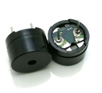
How to identify
A passive buzzer typically has no white covering on top and often looks like a small PCB with a blue or green base. When connected directly to a battery, it will not produce any sound.
Which One to Choose?
Choose an active buzzer if you only need a simple, fixed tone or beep. It works well for basic alerts, alarms, or confirming user input, and it requires minimal setup.
Choose a passive buzzer if you want more control over sound. Since it must be driven by a PWM or square-wave signal, you can generate different tones, melodies, or sound patterns.
For our exercises, a passive buzzer is recommended because it lets us control the output frequency directly (play better tone). However, if you only have an active buzzer, you can still follow along. In fact, I personally used an active buzzer at first for this.
Hardware requirements
- Passive buzzer
- Jumper wires
A buzzer typically has two pins: a positive pin used for the signal and a ground pin. The positive side is often marked with a “+” symbol and is usually the longer pin, while the negative side is shorter, similar to an LED.
That said, some passive buzzers are non-polarized. In those cases, either pin can be connected to the signal or ground. Always check the markings or the datasheet if you are unsure.
Reference
Connecting Buzzer with Raspberry Pi Pico
We will connect GPIO 15 to the buzzer’s positive (signal) pin and the Pico’s GND to the buzzer’s ground pin. You are free to use a different GPIO pin if needed.
| Pico Pin | Wire | Buzzer Pin | Notes |
|---|---|---|---|
| GPIO 15 |
|
Positive Pin | Receives PWM signals to produce sound. |
| GND |
|
Ground Pin | Connects to ground. |
C 实现:蜂鸣
Buzzer Beep Using PWM on Raspberry Pi Pico with Embedded Rust
In this exercise, we will generate a beep sound using a buzzer. The idea is similar to blinking an LED, but instead of toggling a GPIO HIGH and LOW, we control the PWM duty cycle.
We will repeatedly switch the PWM duty cycle between 50 percent and 0 percent, with a delay in between. When the duty cycle is 50 percent, the buzzer produces sound. When it is 0 percent, the sound stops. Repeating this creates a clear beep.
You can try this without changing the PWM frequency. In this example, we set the PWM frequency to 440.0 Hz, which corresponds to the a4 musical note or the call progress tone used in North America and most of Europe. You do not need to know anything about musical notes for this. The important point is that we generate a fixed-frequency tone and turn the sound on and off by changing the duty cycle.
Create Project from template
We will start by creating a new project using the Embassy framework. As usual, generate the project from the template with cargo-generate:
cargo generate --git https://github.com/ImplFerris/pico2-template.git --tag v0.3.2
When prompted, give your project a name like “buzzer-beep” and choose “embassy” as the HAL. Enable defmt logging, if you have a debug probe so you can view logs also.
Additional imports
As we have done before, we import the SetDutyCycle trait and the Pwm and Config types for PWM configuration.
#![allow(unused)]
fn main() {
use embassy_rp::pwm::{Config as PwmConfig, Pwm, SetDutyCycle};
}
Calculate TOP
You can either calculate the TOP value manually or use the calculator form shown in the previous chapter. This time, we will take a different approach.
We will keep the divider fixed at 64 and use a const fn to calculate the TOP value. Since we are not using phase-correct mode or the fractional divider, the calculation is simple.
#![allow(unused)]
fn main() {
const fn get_top(freq: f64, div_int: u8) -> u16 {
    assert!(div_int != 0, "Divider must not be 0");

    let result = 150_000_000. / (freq * div_int as f64);

    assert!(result >= 1.0, "Frequency too high");
    assert!(
        result <= 65535.0,
        "Frequency too low: TOP exceeds 65534 max"
    );

    result as u16 - 1
}

const PWM_DIV_INT: u8 = 64;
const PWM_TOP: u16 = get_top(440., PWM_DIV_INT);
}
Main logic
First, we configure the PWM with the calculated TOP value and the fixed divider. Then we create a PWM output for the buzzer. Inside the loop, we switch the duty cycle between 50 percent and 0 percent with a delay in between, which produces a repeating beep sound.
#![allow(unused)]
fn main() {
let mut pwm_config = PwmConfig::default();
pwm_config.top = PWM_TOP;
pwm_config.divider = PWM_DIV_INT.into();

let mut buzzer = Pwm::new_output_b(p.PWM_SLICE7, p.PIN_15, pwm_config);

loop {
    buzzer
        .set_duty_cycle_percent(50)
        .expect("50 is valid duty percentage");
    Timer::after_millis(1000).await;

    buzzer
        .set_duty_cycle_percent(0)
        .expect("0 is valid duty percentage");
    Timer::after_millis(1000).await;
}
}
If you want the beep to be shorter or faster, you can adjust the delay values.
Clone the existing project
You can clone (or refer to) the project I created and navigate to the buzzer-beep folder.
git clone https://github.com/ImplFerris/pico2-embassy-projects
cd pico2-embassy-projects/buzzer-beep
rp-hal version
If you want to see the same example implemented using rp-hal, you can find it here.
git clone https://github.com/ImplFerris/pico2-rp-projects
cd pico2-rp-projects/buzzer-beep
Playing Songs on a Passive Buzzer Using Rust and Raspberry Pi Pico
In this section, we will play songs on a buzzer using the Raspberry Pi Pico.
If you are not familiar with musical notes or sheet music, you can check the basic theory explained. This part is optional and only meant to give enough background to follow the example.
For clarity, the code is split into Rust modules. You can also keep everything in a single file, as we have done so far, but splitting it makes the example easier to follow:
A passive buzzer is recommended for this exercise, though you can use either a passive or an active buzzer.
PWM
We will use PWM to control the frequency of the signal sent to the buzzer. Each frequency corresponds to a musical note. The frequency (musical note) is held for a specific duration before switching to the next note, based on the music data.
For example, the note a4 is 440 Hz. To play this note, we configure the PWM output to 440 Hz and keep it active for the required duration before moving to the next note.
If you are not familiar with PWM on the Pico, I recommend reading the PWM section before continuing.
Song Repository
In this exercise, we will play a theme on the buzzer as a demonstration.
You can also refer to the rust-embedded-songs repository and try other songs:
https://github.com/ImplFerris/rust-embedded-songs/
Submodules
Update main.rs to define the submodules, then create the corresponding source files.
#![allow(unused)]
fn main() {
pub mod music;
pub mod got;
}
音乐理论
Introduction to Music Notes and Sheet Music
This is a brief guide to music notes and sheet music. While it may not cover everything, it provides a quick reference for key concepts.
Music Sheet
The notes for the music are based on the following sheet. You can refer to this Musescore link for more details.

In music, note durations are represented by the following types, which define how long each note is played:
- Whole note: The longest note duration, lasting for 4 beats.
- Half note: A note that lasts for 2 beats.
- Quarter note: A note that lasts for 1 beat.
- Eighth note: A note that lasts for half a beat, or 1/8th of the duration of a whole note.
- Sixteenth note: A note that lasts for a quarter of a beat, or 1/16th of the duration of a whole note.
Dotted Notes
A dotted note is a note that has a dot next to it. The dot increases the note’s duration by half of its original value. For example:
- Dotted half note: A half note with a dot lasts for 3 beats (2 + 1).
- Dotted quarter note: A quarter note with a dot lasts for 1.5 beats (1 + 0.5).
Tempo and BPM (Beats Per Minute)
Tempo refers to the speed at which a piece of music is played. It is usually measured in beats per minute (BPM), indicating how many beats occur in one minute.
C 实现
Music module (music.rs)
In the music module, we define constants for musical notes and their frequency values.
Each note is stored as an f64 value so it can be used directly when configuring PWM frequency. A special REST value is also defined to represent silence between notes.
#![allow(unused)]
fn main() {
// Note frequencies in Hertz as f64
pub const NOTE_B0: f64 = 31.0;
pub const NOTE_C1: f64 = 33.0;
pub const NOTE_CS1: f64 = 35.0;
pub const NOTE_D1: f64 = 37.0;
pub const NOTE_DS1: f64 = 39.0;
pub const NOTE_E1: f64 = 41.0;
pub const NOTE_F1: f64 = 44.0;
pub const NOTE_FS1: f64 = 46.0;
pub const NOTE_G1: f64 = 49.0;
pub const NOTE_GS1: f64 = 52.0;
pub const NOTE_A1: f64 = 55.0;
pub const NOTE_AS1: f64 = 58.0;
pub const NOTE_B1: f64 = 62.0;
pub const NOTE_C2: f64 = 65.0;
pub const NOTE_CS2: f64 = 69.0;
pub const NOTE_D2: f64 = 73.0;
pub const NOTE_DS2: f64 = 78.0;
pub const NOTE_E2: f64 = 82.0;
pub const NOTE_F2: f64 = 87.0;
pub const NOTE_FS2: f64 = 93.0;
pub const NOTE_G2: f64 = 98.0;
pub const NOTE_GS2: f64 = 104.0;
pub const NOTE_A2: f64 = 110.0;
pub const NOTE_AS2: f64 = 117.0;
pub const NOTE_B2: f64 = 123.0;
pub const NOTE_C3: f64 = 131.0;
pub const NOTE_CS3: f64 = 139.0;
pub const NOTE_D3: f64 = 147.0;
pub const NOTE_DS3: f64 = 156.0;
pub const NOTE_E3: f64 = 165.0;
pub const NOTE_F3: f64 = 175.0;
pub const NOTE_FS3: f64 = 185.0;
pub const NOTE_G3: f64 = 196.0;
pub const NOTE_GS3: f64 = 208.0;
pub const NOTE_A3: f64 = 220.0;
pub const NOTE_AS3: f64 = 233.0;
pub const NOTE_B3: f64 = 247.0;
pub const NOTE_C4: f64 = 262.0;
pub const NOTE_CS4: f64 = 277.0;
pub const NOTE_D4: f64 = 294.0;
pub const NOTE_DS4: f64 = 311.0;
pub const NOTE_E4: f64 = 330.0;
pub const NOTE_F4: f64 = 349.0;
pub const NOTE_FS4: f64 = 370.0;
pub const NOTE_G4: f64 = 392.0;
pub const NOTE_GS4: f64 = 415.0;
pub const NOTE_A4: f64 = 440.0;
pub const NOTE_AS4: f64 = 466.0;
pub const NOTE_B4: f64 = 494.0;
pub const NOTE_C5: f64 = 523.0;
pub const NOTE_CS5: f64 = 554.0;
pub const NOTE_D5: f64 = 587.0;
pub const NOTE_DS5: f64 = 622.0;
pub const NOTE_E5: f64 = 659.0;
pub const NOTE_F5: f64 = 698.0;
pub const NOTE_FS5: f64 = 740.0;
pub const NOTE_G5: f64 = 784.0;
pub const NOTE_GS5: f64 = 831.0;
pub const NOTE_A5: f64 = 880.0;
pub const NOTE_AS5: f64 = 932.0;
pub const NOTE_B5: f64 = 988.0;
pub const NOTE_C6: f64 = 1047.0;
pub const NOTE_CS6: f64 = 1109.0;
pub const NOTE_D6: f64 = 1175.0;
pub const NOTE_DS6: f64 = 1245.0;
pub const NOTE_E6: f64 = 1319.0;
pub const NOTE_F6: f64 = 1397.0;
pub const NOTE_FS6: f64 = 1480.0;
pub const NOTE_G6: f64 = 1568.0;
pub const NOTE_GS6: f64 = 1661.0;
pub const NOTE_A6: f64 = 1760.0;
pub const NOTE_AS6: f64 = 1865.0;
pub const NOTE_B6: f64 = 1976.0;
pub const NOTE_C7: f64 = 2093.0;
pub const NOTE_CS7: f64 = 2217.0;
pub const NOTE_D7: f64 = 2349.0;
pub const NOTE_DS7: f64 = 2489.0;
pub const NOTE_E7: f64 = 2637.0;
pub const NOTE_F7: f64 = 2794.0;
pub const NOTE_FS7: f64 = 2960.0;
pub const NOTE_G7: f64 = 3136.0;
pub const NOTE_GS7: f64 = 3322.0;
pub const NOTE_A7: f64 = 3520.0;
pub const NOTE_AS7: f64 = 3729.0;
pub const NOTE_B7: f64 = 3951.0;
pub const NOTE_C8: f64 = 4186.0;
pub const NOTE_CS8: f64 = 4435.0;
pub const NOTE_D8: f64 = 4699.0;
pub const NOTE_DS8: f64 = 4978.0;
pub const REST: f64 = 0.0; // No sound, for pauses
}
Song structure
We define a small helper struct to represent a song and handle note timing.
#![allow(unused)]
fn main() {
pub struct Song {
    whole_note: u64,
}
}
The whole_note field stores how long a whole note lasts, measured in milliseconds. All other note lengths are calculated from this value. Using milliseconds makes it easy to apply delays when playing notes on a buzzer.
Creating a song
When creating a Song, we calculate the duration of a whole note from the tempo.
#![allow(unused)]
fn main() {
impl Song {
    pub fn new(tempo: u16) -> Self {
        let whole_note = (60_000 * 4) / tempo as u64;
        Self { whole_note }
    }
}
}
Tempo is given in beats per minute. One minute has 60,000 milliseconds, and a whole note is equal to four beats. Dividing by the tempo gives the time, in milliseconds, that one whole note should last.
For example, at 120 BPM, one beat lasts 500 ms, so a whole note lasts 2000 ms.
Calculating note duration
This method converts a note value into a time duration.
#![allow(unused)]
fn main() {
pub fn calc_note_duration(&self, divider: i16) -> u64 {
    if divider > 0 {
        self.whole_note / divider as u64
    } else {
        let duration = self.whole_note / divider.unsigned_abs() as u64;
        (duration as f64 * 1.5) as u64
    }
}
}
The divider tells the code how the note relates to a whole note. A value of 1 means a whole note. A value of 2 means a half note. A value of 4 means a quarter note. The duration is calculated by dividing the whole note duration by this value.
Negative values are used to represent dotted notes. A dotted note lasts one and a half times longer than the normal version of the same note. When the divider is negative, the code first calculates the normal duration using the absolute value, then multiplies it by 1.5.
This positive and negative logic is a custom approach (based on an Arduino example I referred to) to differentiate dotted notes. It is not part of standard musical notation.
Melody Example: Game of Thrones Theme
This section contains code snippets for the Rust module got.
Importing music definitions
The got module uses note constants and helper types defined in the music module. We bring them into scope using the following import:
#![allow(unused)]
fn main() {
use crate::music::*;
}
This allows the melody to use note constants like NOTE_E4 and NOTE_A4 directly, without writing the module name each time.
Tempo
We declare the tempo for the song. You can change this value and observe how it affects playback speed.
#![allow(unused)]
fn main() {
pub const TEMPO: u16 = 85;
}
Melody Array
We define the melody of the Game of Thrones theme as an array of notes and durations. Each entry is a tuple containing a note frequency and its duration.
The duration is represented by an integer. Positive values represent normal notes. Negative values represent dotted notes.
#![allow(unused)]
fn main() {
pub const MELODY: [(f64, i16); 92] = [
    // Game of Thrones Theme
    (NOTE_G4, 8),
    (NOTE_C4, 8),
    (NOTE_DS4, 16),
    (NOTE_F4, 16),
    (NOTE_G4, 8),
    (NOTE_C4, 8),
    (NOTE_DS4, 16),
    (NOTE_F4, 16),
    (NOTE_G4, 8),
    (NOTE_C4, 8),
    (NOTE_DS4, 16),
    (NOTE_F4, 16),
    (NOTE_G4, 8),
    (NOTE_C4, 8),
    (NOTE_DS4, 16),
    (NOTE_F4, 16),
    (NOTE_G4, 8),
    (NOTE_C4, 8),
    (NOTE_E4, 16),
    (NOTE_F4, 16),
    (NOTE_G4, 8),
    (NOTE_C4, 8),
    (NOTE_E4, 16),
    (NOTE_F4, 16),
    (NOTE_G4, 8),
    (NOTE_C4, 8),
    (NOTE_E4, 16),
    (NOTE_F4, 16),
    (NOTE_G4, 8),
    (NOTE_C4, 8),
    (NOTE_E4, 16),
    (NOTE_F4, 16),
    (NOTE_G4, -4),
    (NOTE_C4, -4),
    (NOTE_DS4, 16),
    (NOTE_F4, 16),
    (NOTE_G4, 4),
    (NOTE_C4, 4),
    (NOTE_DS4, 16),
    (NOTE_F4, 16),
    (NOTE_D4, -1),
    (NOTE_F4, -4),
    (NOTE_AS3, -4),
    (NOTE_DS4, 16),
    (NOTE_D4, 16),
    (NOTE_F4, 4),
    (NOTE_AS3, -4),
    (NOTE_DS4, 16),
    (NOTE_D4, 16),
    (NOTE_C4, -1),
    // Repeat
    (NOTE_G4, -4),
    (NOTE_C4, -4),
    (NOTE_DS4, 16),
    (NOTE_F4, 16),
    (NOTE_G4, 4),
    (NOTE_C4, 4),
    (NOTE_DS4, 16),
    (NOTE_F4, 16),
    (NOTE_D4, -1),
    (NOTE_F4, -4),
    (NOTE_AS3, -4),
    (NOTE_DS4, 16),
    (NOTE_D4, 16),
    (NOTE_F4, 4),
    (NOTE_AS3, -4),
    (NOTE_DS4, 16),
    (NOTE_D4, 16),
    (NOTE_C4, -1),
    (NOTE_G4, -4),
    (NOTE_C4, -4),
    (NOTE_DS4, 16),
    (NOTE_F4, 16),
    (NOTE_G4, 4),
    (NOTE_C4, 4),
    (NOTE_DS4, 16),
    (NOTE_F4, 16),
    (NOTE_D4, -2),
    (NOTE_F4, -4),
    (NOTE_AS3, -4),
    (NOTE_D4, -8),
    (NOTE_DS4, -8),
    (NOTE_D4, -8),
    (NOTE_AS3, -8),
    (NOTE_C4, -1),
    (NOTE_C5, -2),
    (NOTE_AS4, -2),
    (NOTE_C4, -2),
    (NOTE_G4, -2),
    (NOTE_DS4, -2),
    (NOTE_DS4, -4),
    (NOTE_F4, -4),
    (NOTE_G4, -1),
];
}
Rust 代码
Playing the Game of Thrones Melody
In this section, we put everything together and work in the main.rs file.
By this point, we already have the note frequencies, song timing logic, and melody data. Here, we just wire them together using PWM and timers.
Imports
Add the required imports for PWM, timers, and song handling.
#![allow(unused)]
fn main() {
// For PWM
use embassy_rp::pwm::{Config as PwmConfig, Pwm, SetDutyCycle};

use crate::music::Song;
}
PWM and Buzzer
Unlike the previous example, we clone PwmConfig. The Pwm constructor consumes the config object, but inside the loop we need to modify top to change the PWM frequency for each musical note.
#![allow(unused)]
fn main() {
let mut pwm_config = PwmConfig::default();
pwm_config.top = PWM_TOP;
pwm_config.divider = PWM_DIV_INT.into();

let mut buzzer = Pwm::new_output_b(p.PWM_SLICE7, p.PIN_15, pwm_config.clone());
}
Create the Song object
Create a Song using the tempo defined for the Game of Thrones theme.
#![allow(unused)]
fn main() {
let song = Song::new(got::TEMPO);
}
Playing the notes
The melody is played by looping through the MELODY array. Each entry contains a note frequency and a duration value.
#![allow(unused)]
fn main() {
// One time play the song
for (note, duration_type) in got::MELODY {
    let top = get_top(note, PWM_DIV_INT);
    pwm_config.top = top;
    buzzer.set_config(&pwm_config);

    let note_duration = song.calc_note_duration(duration_type);
    let pause_duration = note_duration / 10; // 10% of note_duration

    buzzer
        .set_duty_cycle_percent(50)
        .expect("50 is valid duty percentage"); // Set duty cycle to 50% to play the note

    Timer::after_millis(note_duration - pause_duration).await; // Play 90%

    buzzer
        .set_duty_cycle_percent(0)
        .expect("50 is valid duty percentage"); // Stop tone
    Timer::after_millis(pause_duration).await; // Pause for 10%
}
}
For each note, the PWM frequency is updated by setting a new top value. This makes the buzzer produce the correct pitch.
The note duration is calculated from the song tempo. Most of that time is spent playing the note, and a small part is left silent. That short silence helps separate notes so the melody sounds cleaner.
The buzzer is played by setting the duty cycle to 50 percent and stopped by setting it to zero.
Keeping the Program Running
After the melody finishes, this is just to keep the program alive.
#![allow(unused)]
fn main() {
loop {
    Timer::after_millis(100).await;
}
}
Clone the existing project
You can clone (or refer to) the project I created and navigate to the buzzer-song folder.
git clone https://github.com/ImplFerris/pico2-embassy-projects
cd pico2-embassy-projects/buzzer-song
rp-hal version
If you want to see the same example implemented using rp-hal, you can find it here.
git clone https://github.com/ImplFerris/pico2-rp-projects
cd pico2-rp-projects/got-buzzer
Beeping with an Active Buzzer
Since you already know how an active buzzer works, we can make it beep by simply turning a GPIO pin on and off. In this exercise, we use a GPIO pin to power the buzzer, wait for a short time, turn it off, and repeat. This creates a clear beeping sound.
Note
This example is meant for an active buzzer. If you use a passive buzzer instead, the sound may be strange or inconsistent. Try this exercise only with an active buzzer.
Hardware Requirements
- Active buzzer
- Jumper wires (female-to-male or male-to-male, depending on your setup)
Project from template
Create a new project:
To set up the project, run:
cargo generate --git https://github.com/ImplFerris/pico2-template.git --tag v0.3.2
When prompted, give your project a name, like “active-beep” and select embassy as the HAL.
Main logic
Ensure the buzzer is connected to GPIO 15. The pin is toggled every 500 milliseconds to turn the buzzer on and off.
#![allow(unused)]
fn main() {
let mut buzzer = Output::new(p.PIN_15, Level::Low);

loop {
    buzzer.set_high();
    Timer::after_millis(500).await;

    buzzer.set_low();
    Timer::after_millis(500).await;
}
}
Clone the existing project
You can clone (or refer) project I created and navigate to the active-beep folder.
git clone https://github.com/ImplFerris/pico2-embassy-projects
cd pico2-embassy-projects/active-beep
Voltage Divider
A voltage divider is a simple circuit that reduces a higher input voltage to a lower output voltage using two resistors connected in series. You might need a voltage divider from time to time when working with sensors or modules that output higher voltages than your microcontroller can safely handle.
The resistor connected to the input voltage is called \( R_{1} \), and the resistor connected to ground is called \( R_{2} \). The output voltage \( V_{out} \) is measured at the point between \( R_{1} \) and \( R_{2} \), and it will be a fraction of the input voltage \( V_{in} \).
Circuit
The output voltage (Vout) is calculated using this formula:
\[ V_{out} = V_{in} \times \frac{R_2}{R_1 + R_2} \]
Example Calculation for \( V_{out} \)
Given:
- \( V_{in} = 3.3 V \)
- \( R_1 = 10 k\Omega \)
- \( R_2 = 10 k\Omega \)
Substitute the values:
\[ V_{out} = 3.3 V \times \frac{10 k\Omega}{10 k\Omega + 10 k\Omega} = 3.3 V \times \frac{10}{20} = 3.3 V \times 0.5 = 1.65 V \]
The output voltage \( V_{out} \) is 1.65 V.
fn main() {
    // You can edit the code
    // You can modify values and run the code
    let vin: f64 = 3.3;
    let r1: f64 = 10000.0;
    let r2: f64 = 10000.0;

    let vout = vin * (r2 / (r1 + r2));

    println!("The output voltage Vout is: {:.2} V", vout);
}
Use cases
Voltage dividers are used in applications like potentiometers, where the resistance changes as the knob is rotated, adjusting the output voltage. They are also used to measure resistive sensors such as light sensors and thermistors, where a known voltage is applied, and the microcontroller reads the voltage at the center node to determine sensor values like temperature.
Voltage Divider Simulation
Formula: Vout = Vin × (R2 / (R1 + R2))
Filled Formula: Vout = 3.3 × (10000 / (10000 + 10000))
Output Voltage (Vout): 1.65 V
Simulator in Falstad website
I used the website https://www.falstad.com/circuit/ to create the diagram. It’s a great tool for drawing circuits. You can download the file I created, voltage-divider.circuitjs.txt, and import it to experiment with the circuit.
Bat Beacon: Distance Sensor Project 🦇
If you’ve seen the Batman Begins movie, you’ll remember the scene where Batman uses a device that emits ultrasonic signals to summon a swarm of bats. It’s one of the coolest gadgets in his arsenal! While we won’t be building a bat-summoning beacon today, we will be working with the similar ultrasonic technology.
Ultrasonic
Ultrasonic waves are sound waves with frequencies above 20,000 Hz, beyond what human ears can detect, but many animals can. Bats use ultrasonic waves to fly in the dark and avoid obstacles. Dolphins use them to communicate and to sense objects underwater.
Ultrasonic Technology Around You
Humans have borrowed this natural sonar principle for everyday inventions:
- Car parking sensors use ultrasonic sensors to detect obstacles when you reverse. As you get closer to an object, the beeping gets faster.
- Submarines use sonar to navigate and detect underwater objects
- Medical ultrasound allows doctors to see inside the human body
- Automatic doors and robot navigation rely on ultrasonic distance sensing
Today, you’ll build your own distance sensor using an ultrasonic module; sending out sound waves, measuring how long they take to bounce back, and calculating distance.
Meet the Hardware
The HC-SR04+ is a simple and low cost ultrasonic distance sensor. It can measure distances from about 2 cm up to 400 cm. It works by sending out a short burst of ultrasonic sound and then listening for the echo. By measuring how long the echo takes to return, the sensor can calculate how far the object is.
Tip
The HC-SR04 normally operates at 5 V, which can be problematic for the Raspberry Pi Pico. If possible, purchase the HC-SR04+ version, which works with both 3.3 V and 5 V, making it more suitable for the Pico.
Why This Matters: The HC-SR04’s Echo pin outputs a 5 V signal, but the Pico’s GPIO pins can only safely handle 3.3 V. Connecting 5 V directly to the Pico could damage it.
Your Options:
- Buy the HC-SR04+ variant (recommended and easiest solution)
- Use a voltage divider on the Echo pin to reduce the 5 V signal to 3.3 V
- Use a logic level converter to safely step down the voltage
- Power the HC-SR04 with 3.3 V (not recommended, as it may work unreliably or not at all)
In this project, we’ll build a proximity detector that gradually brightens an LED as objects get closer. When the sensor detects something within 30 cm, the LED will glow brighter using PWM. You can change the distance value if you want to try different ideas.
Prerequisites
Before starting, get familiar with yourself on these topics
Hardware Requirements
To complete this project, you will need:
- HC-SR04+ or HC-SR04 Ultrasonic Sensor
- Breadboard
- Jumper wires
- External LED (You can also use the onboard LED, but you’ll need to modify the code accordingly)
- If you are using the standard HC-SR04 module that operates at 5 V, you will need two resistors (1 kΩ and 2 kΩ or 2.2 kΩ) to form a voltage divider.
The HC-SR04 Sensor module has a transmitter and receiver. The module has Trigger and Echo pins which can be connected to the GPIO pins of a pico. When the receiver detects the returning sound wave, the Echo pin goes HIGH for a duration equal to the time it takes for the wave to return to the sensor.
Datasheet
Most electronic components come with a datasheet. It’s a technical document that tells you everything you need to know about how the component works, its electrical characteristics, and how to use it properly.
For the HC-SR04 ultrasonic sensor, you can find the datasheet here: https://cdn.sparkfun.com/datasheets/Sensors/Proximity/HCSR04.pdf
Datasheets can look intimidating at first with all their technical specifications and diagrams, but you don’t need to understand everything in them.
How Does an Ultrasonic Sensor Work?
Ultrasonic sensors work by emitting sound waves at a frequency too high (40 kHz) for humans to hear. These sound waves travel through the air and bounce back when they hit an object. The sensor calculates the distance by measuring how long it takes for the sound waves to return.
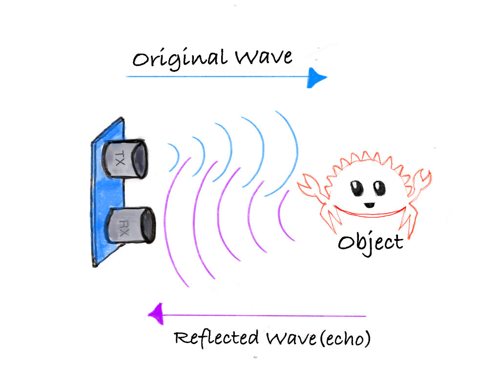
- Transmitter: Sends out ultrasonic sound waves.
- Receiver: Detects the sound waves that bounce back from an object.
Formula to calculate distance:
Distance = (Time x Speed of Sound) / 2
The speed of sound is approximately 0.0343 cm/µs (or 343 m/s) at normal air pressure and a temperature of 20 °C.
Example Calculation
Let’s say the ultrasonic sensor detects that the sound wave took 2000 µs to return after hitting an object.
Step 1: Calculate the total distance traveled by the sound wave:
Total distance = Time x Speed of Sound
Total distance = 2000 µs x 0.0343 cm/µs = 68.6 cm
Step 2: Since the sound wave traveled to the object and back, the distance to the object is half of the total distance:
Distance to object = 68.6 cm / 2 = 34.3 cm
Thus, the object is 34.3 cm away from the sensor.
HC-SR04 Pinout
The module has four pins: VCC, Trig, Echo, and GND.
| Pin | Function |
|---|---|
| VCC | Power Supply |
| Trig | Trigger Signal |
| Echo | Echo Signal |
| GND | Ground |
Measuring Distance with the HC-SR04 module
The HC-SR04 module has a transmitter and receiver, responsible for sending ultrasonic waves and detecting the reflected waves. We will use the Trig pin to send sound waves. And read from the Echo pin to measure the distance.
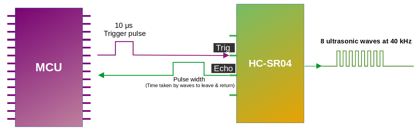
As you can see in the diagram, we connect the Trig and Echo pins to the GPIO pins of the microcontroller (we also connect VCC and GND but left them out to keep the illustration simple). We send ultrasonic waves by setting the Trig pin HIGH for 10 microseconds and then setting it back to LOW. This triggers the module to send 8 consecutive ultrasonic waves at a frequency of 40 kHz. It is recommended to have a minimum gap of 50 ms between each trigger.
When the sensor’s waves hit an object, they bounce back to the module. As you can see in the diagram, the Echo pin changes the signal sent to the microcontroller, with the length of time the signal stays HIGH (pulse width) corresponding to the distance. In the microcontroller, we measure how long the Echo pin stays HIGH; Then, we can use this time duration to calculate the distance to the object.
Pulse width and the distance:
The pulse width (amount of time it stays high) produced by the Echo pin will range from about 150 µs to 25,000 µs (25 ms); this is only if it hits an object. If there is no object, it will produce a pulse width of around 38 ms.
Wiring the HC-SR04 to the Pico 2 Using a Voltage Divider
If you are using the regular HC-SR04 like I am, you will need to create a voltage divider for the Echo pin. In this section we will look at how to set up the circuit. However, if you are lucky and you bought the HC-SR04 Plus, you can skip to the next page. The circuit becomes much simpler because you can power the sensor with 3.3 V instead of 5 V.
Common resistor combination
Below are some resistor pairs you can use to bring the HC-SR04 Echo signal down to about 3.3 V. R1 is the resistor connected to the Echo pin, and R2 is the resistor connected to ground.
| R1 (With Echo) | R2 (With Gnd) | Output Voltage |
|---|---|---|
| 330 Ω | 470 Ω | 2.94 V |
| 330 Ω | 680 Ω | 3.37 V |
| 470 Ω | 680 Ω | 2.96 V |
| 680 Ω | 1 kΩ | 2.98 V |
| 1 kΩ | 1.8 kΩ | 3.21 V |
| 1 kΩ | 2 kΩ | 3.33 V |
| 1 kΩ | 2.2 kΩ | 3.44 V |
| 1.5 kΩ | 2.2 kΩ | 2.97 V |
| 2.2 kΩ | 3.3 kΩ | 3.00 V |
| 3.3 kΩ | 4.7 kΩ | 2.94 V |
| 4.7 kΩ | 6.8 kΩ | 2.96 V |
| 6.8 kΩ | 10 kΩ | 2.98 V |
| 22 kΩ | 33 kΩ | 3.00 V |
| 33 kΩ | 47 kΩ | 2.94 V |
| 47 kΩ | 68 kΩ | 2.96 V |
You can choose any resistor pair from the table because all of them bring the 5 V Echo signal down to a safe level near 3.3 V. In practice it is best to use the values you already have in your kit.r
Connection for the Raspberry Pi Pico 2 and Ultrasonic Sensor
| Pico 2 Pin | Wire | HC-SR04 Pin |
|---|---|---|
| VBUS (Pin 40) |
|
VCC |
| GPIO 17 |
|
Trig |
| GPIO 16 (via Voltage Divider) |
|
Echo (through 1 kΩ/2.2 kΩ divider) |
| GND |
|
GND |
- VCC: Connect the VCC pin on the HC-SR04 to VBUS (Pin 40) on the Pico 2. The HC-SR04 requires 5 V power, and VBUS provides 5 V from the USB connection.
- Trig: Connect to GPIO 17 on the Pico 2 to trigger the ultrasonic sound pulses.
- Echo: Connect to GPIO 16 on the Pico 2 through a voltage divider (1 kΩ resistor from Echo pin, 2 kΩ or 2.2 kΩ resistor to ground). The junction between the resistors connects to GPIO 16. This divider steps down the 5 V Echo signal to ~3.4 V, protecting the Pico’s 3.3 V GPIO pins.
- GND: Connect to any ground pin on the Pico 2.
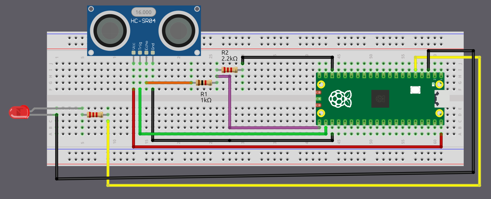
Connection for the Pico 2 and LED
| Pico 2 Pin | Wire | Component |
|---|---|---|
| GPIO 3 |
|
Resistor (220 Ω-330 Ω) |
| Resistor |
|
Anode (long leg) of LED |
| GND |
|
Cathode (short leg) of LED |
Circuit for HC-SR04+
Skip this step if you are using the 5 V-only variant of the HC-SR04.
Connection for the Pico and Ultrasonic:
| Pico Pin | Wire | HC-SR04+ Pin |
|---|---|---|
| 3.3 V |
|
VCC |
| GPIO 17 |
|
Trig |
| GPIO 16 |
|
Echo |
| GND |
|
GND |
- VCC: Connect the VCC pin on the HC-SR04+ to the 3.3 V pin on the Pico.
- Trig: Connect to GPIO 17 on the Pico to start the ultrasonic sound pulses.
- Echo: Connect to GPIO 16 on the Pico; this pin sends a pulse when it detects the reflected signal, and the pulse length shows how long the signal took to return.
- GND: Connect to the ground pin on the Pico.
- LED: Connect the anode (long leg) of the LED to GPIO 3.
Connection for the Pico and LED:
| Pico Pin | Wire | Component |
|---|---|---|
| GPIO 3 |
|
Resistor |
| Resistor |
|
Anode (long leg) of LED |
| GND |
|
Cathode (short leg) of LED |
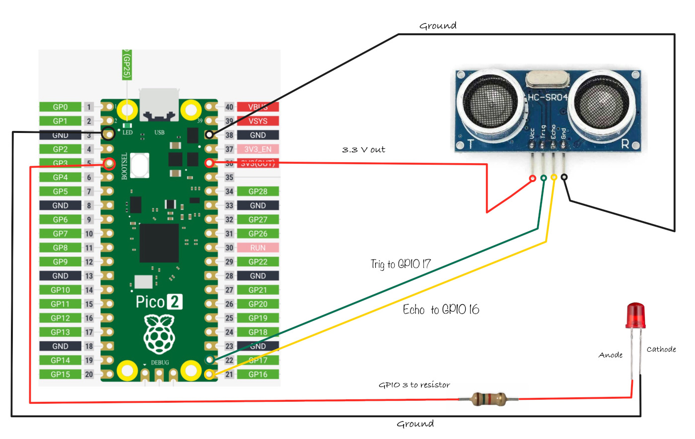
C 实现
Rust Tutorial: Using the HC-SR04 Sensor with the Pico 2
We will start by creating a new project using the Embassy framework. After that, we wll build the same project again using rp-hal. As usual, generate the project from the template with cargo-generate:
cargo generate --git https://github.com/ImplFerris/pico2-template.git --tag v0.3.2
When prompted, give your project a name like bat-beacon and choose embassy as the HAL. Enable defmt logging, if you have a debug probe so you can view logs also.
Additional Imports
In addition to the usual boilerplate imports, you’ll need to add these specific imports to your project. Your code editor should provide auto-import suggestions for most of these, with the exception of the SetDutyCycle trait which you’ll need to add manually.
#![allow(unused)]
fn main() {
// For GPIO
use embassy_rp::gpio::{Input, Level, Output, Pull};

// For PWM
use embassy_rp::pwm::{Pwm, SetDutyCycle};

// For time calculation
use embassy_time::Instant;
}
We need GPIO types to control our trigger and echo pins, PWM to control the LED brightness, and timing utilities to measure the ultrasonic pulse duration.r
Mapping GPIO Pins
By now, you should be familiar with PWM from the Dimming LED section. We will create a similar dimming effect here. But there’s a key difference. In the Dimming LED chapter, we made the LED fade in and out repeatedly using conditions. Here, we will increase the LED brightness only when an object gets closer to the sensor.
#![allow(unused)]
fn main() {
// For Onboard LED
// let mut led = Pwm::new_output_b(p.PWM_SLICE4, p.PIN_25, Default::default());

// For external LED connected on GPIO 3
let mut led = Pwm::new_output_b(p.PWM_SLICE1, p.PIN_3, Default::default());
}
You can use either the onboard LED or an external LED. I prefer using the external LED. You can see the gradual brightness changes much better.
Next, let’s initialize the LED to be off and get its maximum duty cycle value:
#![allow(unused)]
fn main() {
led.set_duty_cycle(0)
.expect("duty cycle is within valid range");
let max_duty = led.max_duty_cycle();
// defmt::info!("Max duty cycle {}", max_duty);
}The duty cycle determines LED brightness; 0 is completely off, and max_duty is fully on.
Configuring Trigger and Echo Pins
As you know, we have to send a signal to the trigger pin from the Pico, so we’ll configure GPIO pin 17 (connected to the trigger pin) as an Output with an initial Low state. The sensor indicates distance through pulses on the echo pin, meaning it sends signals to the Pico (input to the Pico). So we’ll configure GPIO pin 16 (connected to the echo pin) as an Input.
#![allow(unused)]
fn main() {
let mut trigger = Output::new(p.PIN_17, Level::Low);
let echo = Input::new(p.PIN_16, Pull::Down);
}Converting Distance to LED Brightness
We need a function that converts distance measurements into appropriate duty cycle values. The closer an object is, the higher the duty cycle (brighter the LED):
#![allow(unused)]
fn main() {
const MAX_DISTANCE_CM: f64 = 30.0;
fn calculate_duty_cycle(distance: f64, max_duty: u16) -> u16 {
if distance < MAX_DISTANCE_CM && distance >= 2.0 {
let normalized = (MAX_DISTANCE_CM - distance) / MAX_DISTANCE_CM;
// defmt::info!("duty cycle :{}", (normalized * max_duty as f64) as u16);
(normalized * max_duty as f64) as u16
} else {
0
}
}
}This function takes the measured distance and the maximum duty cycle value. If the distance is between 2 cm (the sensor’s minimum range) and 30 cm, we normalize it to a 0-1 range and multiply by the maximum duty cycle. Objects closer than 2 cm or farther than 30 cm result in the LED turning off (duty cycle of 0).
Measuring Distance with the Sensor
We’ll measure distance by sending an ultrasonic pulse and timing how long it takes to return:
#![allow(unused)]
fn main() {
const ECHO_TIMEOUT: Duration = Duration::from_millis(100);
async fn measure_distance(trigger: &mut Output<'_>, echo: &Input<'_>) -> Option<f64> {
// Send trigger pulse
trigger.set_low();
Timer::after_micros(2).await;
trigger.set_high();
Timer::after_micros(10).await;
trigger.set_low();
// Wait for echo HIGH (sensor responding)
let timeout = Instant::now();
while echo.is_low() {
if timeout.elapsed() > ECHO_TIMEOUT {
defmt::warn!("Timeout waiting for HIGH");
return None; // Return early on timeout
}
}
let start = Instant::now();
// Wait for echo LOW (pulse complete)
let timeout = Instant::now();
while echo.is_high() {
if timeout.elapsed() > ECHO_TIMEOUT {
defmt::warn!("Timeout waiting for LOW");
return None; // Return early on timeout
}
}
let end = Instant::now();
// Calculate distance
let time_elapsed = end.checked_duration_since(start)?.as_micros();
let distance = time_elapsed as f64 * 0.0343 / 2.0;
Some(distance)
}
}We begin by setting the trigger pin low for a brief moment, then raising it high for 10 microseconds. This creates the trigger pulse that instructs the sensor to emit an ultrasonic burst. After that, we wait for the Echo pin to rise. The time the Echo pin stays high represents the round-trip travel time of the sound wave. Using this duration, we compute the final distance value and return it.
We have also added a timeout while waiting for the echo pin to change state so the code does not get stuck indefinitely. When the pin fails to respond within the allowed time, we treat the attempt as a failed reading and return None, which lets the rest of the program continue running normally.
The main loop
Finally, let’s create our main loop that continuously reads the sensor and updates the LED:
#![allow(unused)]
fn main() {
loop {
Timer::after_millis(10).await;
let distance = match measure_distance(&mut trigger, &echo).await {
Some(d) => d,
None => {
Timer::after_secs(5).await;
continue; // Skip to next iteration
}
};
let duty_cycle = calculate_duty_cycle(distance, max_duty);
led.set_duty_cycle(duty_cycle)
.expect("duty cycle is within valid range");
}
}Every 10 milliseconds, we measure the distance. If the measurement succeeds, we calculate the appropriate LED brightness and apply it. If it fails (due to timeout or sensor issues), we wait 5 seconds before trying again.
The Full code
Here’s everything put together:
#![no_std]
#![no_main]
use embassy_executor::Spawner;
use embassy_rp as hal;
use embassy_rp::block::ImageDef;
use embassy_time::{Duration, Timer};
//Panic Handler
use panic_probe as _;
// Defmt Logging
use defmt_rtt as _;
// For GPIO
use embassy_rp::gpio::{Input, Level, Output, Pull};
// For PWM
use embassy_rp::pwm::{Pwm, SetDutyCycle};
// For time calculation
use embassy_time::Instant;
/// Tell the Boot ROM about our application
#[unsafe(link_section = ".start_block")]
#[used]
pub static IMAGE_DEF: ImageDef = hal::block::ImageDef::secure_exe();
#[embassy_executor::main]
async fn main(_spawner: Spawner) {
let p = embassy_rp::init(Default::default());
// For Onboard LED
// let mut led = Pwm::new_output_b(p.PWM_SLICE4, p.PIN_25, Default::default());
// For external LED connected on GPIO 3
let mut led = Pwm::new_output_b(p.PWM_SLICE1, p.PIN_3, Default::default());
let mut trigger = Output::new(p.PIN_17, Level::Low);
let echo = Input::new(p.PIN_16, Pull::None);
led.set_duty_cycle(0)
.expect("duty cycle is within valid range");
let max_duty = led.max_duty_cycle();
// defmt::info!("Max duty cycle {}", max_duty);
loop {
Timer::after_millis(10).await;
let distance = match measure_distance(&mut trigger, &echo).await {
Some(d) => d,
None => {
Timer::after_secs(5).await;
continue; // Skip to next iteration
}
};
let duty_cycle = calculate_duty_cycle(distance, max_duty);
led.set_duty_cycle(duty_cycle)
.expect("duty cycle is within valid range");
}
}
const ECHO_TIMEOUT: Duration = Duration::from_millis(100);
async fn measure_distance(trigger: &mut Output<'_>, echo: &Input<'_>) -> Option<f64> {
// Send trigger pulse
trigger.set_low();
Timer::after_micros(2).await;
trigger.set_high();
Timer::after_micros(10).await;
trigger.set_low();
// Wait for echo HIGH (sensor responding)
let timeout = Instant::now();
while echo.is_low() {
if timeout.elapsed() > ECHO_TIMEOUT {
defmt::warn!("Timeout waiting for HIGH");
return None; // Return early on timeout
}
}
let start = Instant::now();
// Wait for echo LOW (pulse complete)
let timeout = Instant::now();
while echo.is_high() {
if timeout.elapsed() > ECHO_TIMEOUT {
defmt::warn!("Timeout waiting for LOW");
return None; // Return early on timeout
}
}
let end = Instant::now();
// Calculate distance
let time_elapsed = end.checked_duration_since(start)?.as_micros();
let distance = time_elapsed as f64 * 0.0343 / 2.0;
Some(distance)
}
const MAX_DISTANCE_CM: f64 = 30.0;
fn calculate_duty_cycle(distance: f64, max_duty: u16) -> u16 {
if distance < MAX_DISTANCE_CM && distance >= 2.0 {
let normalized = (MAX_DISTANCE_CM - distance) / MAX_DISTANCE_CM;
// defmt::info!("duty cycle :{}", (normalized * max_duty as f64) as u16);
(normalized * max_duty as f64) as u16
} else {
0
}
}
// Program metadata for `picotool info`.
// This isn't needed, but it's recomended to have these minimal entries.
#[unsafe(link_section = ".bi_entries")]
#[used]
pub static PICOTOOL_ENTRIES: [embassy_rp::binary_info::EntryAddr; 4] = [
embassy_rp::binary_info::rp_program_name!(c"ultrasonic"),
embassy_rp::binary_info::rp_program_description!(c"your program description"),
embassy_rp::binary_info::rp_cargo_version!(),
embassy_rp::binary_info::rp_program_build_attribute!(),
];
// End of fileClone the existing project
You can clone (or refer) project I created and navigate to the ultrasonic folder.
git clone https://github.com/ImplFerris/pico2-embassy-projects
cd pico2-embassy-projects/ultrasonic
Writing Rust Code Use HC-SR04 Ultrasonic Sensor with Pico 2
We’ll start by generating the project using the template, then modify the code to fit the current project’s requirements.
Generating From template
Refer to the Template section for details and instructions.
To generate the project, run:
cargo generate --git https://github.com/ImplFerris/pico2-template.git --tag v0.3.2
When prompted, choose a name for your project-let’s go with “bat-beacon”. Don’t forget to select rp-hal as the HAL.
Then, navigate into the project folder:
cd PROJECT_NAME
# For example, if you named your project "bat-beacon":
# cd bat-beacon
Setup the LED Pin
You should understand this code by now. If not, please complete the Blink LED section first.
Quick recap: Here, we’re configuring the PWM for the LED, which allows us to control the brightness by adjusting the duty cycle.
#![allow(unused)]
fn main() {
let pwm = &mut pwm_slices.pwm1; // Access PWM slice 1
pwm.set_ph_correct(); // Set phase-correct mode for smoother transitions
pwm.enable(); // Enable the PWM slice
let led = &mut pwm.channel_b; // Select PWM channel B
led.output_to(pins.gpio3); // Set GPIO 3 as the PWM output pin
}Setup the Trigger Pin
The Trigger pin on the ultrasonic sensor is used to start the ultrasonic pulse. It needs to be set as an output so we can control it to send the pulse.
#![allow(unused)]
fn main() {
let mut trigger = pins.gpio17.into_push_pull_output();
}Setup the Echo Pin
The Echo pin on the ultrasonic sensor receives the returning signal, which allows us to measure the time it took for the pulse to travel to an object and back. It’s set as an input to detect the returning pulse.
#![allow(unused)]
fn main() {
let mut echo = pins.gpio16.into_pull_down_input();
}🦇 Light it Up
Step 1: Send the Trigger Pulse
First, we need to send a short pulse to the trigger pin to start the ultrasonic measurement.
#![allow(unused)]
fn main() {
// Ensure the Trigger pin is low before starting
trigger.set_low().ok().unwrap();
timer.delay_us(2);
// Send a 10-microsecond high pulse
trigger.set_high().ok().unwrap();
timer.delay_us(10);
trigger.set_low().ok().unwrap();
}Step 2: Measure the Echo Time
Next, we will use two loops. The first loop will run as long as the echo pin state is LOW. Once it goes HIGH, we will record the current time in a variable. Then, we start the second loop, which will continue as long as the echo pin remains HIGH. When it returns to LOW, we will record the current time in another variable. The difference between these two times gives us the pulse width.
#![allow(unused)]
fn main() {
let mut time_low = 0;
let mut time_high = 0;
// Wait for the Echo pin to go high and note down the time
while echo.is_low().ok().unwrap() {
time_low = timer.get_counter().ticks();
}
// Wait for the Echo pin to go low and note down the time
while echo.is_high().ok().unwrap() {
time_high = timer.get_counter().ticks();
}
// Calculate the time taken for the signal to return
let time_passed = time_high - time_low;
}Step 3: Calculate Distance
To calculate the distance, we need to use the pulse width. The pulse width tells us how long it took for the ultrasonic waves to travel to an obstacle and return. Since the pulse represents the round-trip time, we divide it by 2 to account for the journey to the obstacle and back.
The speed of sound in air is approximately 0.0343 cm per microsecond. By multiplying the time (in microseconds) by this value and dividing by 2, we obtain the distance to the obstacle in centimeters.
#![allow(unused)]
fn main() {
let distance = time_passed as f64 * 0.0343 / 2.0;
}Step 4: PWM Duty cycle for LED
Finally, we adjust the LED brightness based on the measured distance.
The duty cycle percentage is calculated using our own logic, you can modify it to suit your needs. When the object is closer than 30 cm, the LED brightness will increase. The closer the object is to the ultrasonic module, the higher the calculated ratio will be, which in turn adjusts the duty cycle. This results in the LED brightness gradually increasing as the object approaches the sensor.
#![allow(unused)]
fn main() {
let duty_cycle = if distance < 30.0 {
let step = 30.0 - distance;
(step * 1500.) as u16 + 1000
} else {
0
};
// Change the LED brightness
led.set_duty_cycle(duty_cycle).unwrap();
}Complete Logic of the loop
Note: This code snippet highlights the loop section and does not include the entire code.
#![allow(unused)]
fn main() {
loop {
timer.delay_ms(5);
trigger.set_low().ok().unwrap();
timer.delay_us(2);
trigger.set_high().ok().unwrap();
timer.delay_us(10);
trigger.set_low().ok().unwrap();
let mut time_low = 0;
let mut time_high = 0;
while echo.is_low().ok().unwrap() {
time_low = timer.get_counter().ticks();
}
while echo.is_high().ok().unwrap() {
time_high = timer.get_counter().ticks();
}
let time_passed = time_high - time_low;
let distance = time_passed as f64 * 0.0343 / 2.0;
let duty_cycle = if distance < 30.0 {
let step = 30.0 - distance;
(step * 1500.) as u16 + 1000
} else {
0
};
led.set_duty_cycle(duty_cycle).unwrap();
}
}Clone the existing project
You can clone (or refer) project I created and navigate to the ultrasonic folder.
git clone https://github.com/ImplFerris/pico2-rp-projects
cd pico2-rp-projects/ultrasonic
Your Challenge
- Use Embassy framework instead of
rp-hal - Use the onboard LED instead
Interrupts
Just give me a minute, my partner is calling.
Yes honey. Sure, I will do.
Ok, I am back. So, where was I?
When an interrupt occurs, the processor pauses its current execution.
Just a moment, someone is ringing the doorbell.
Nice, the Pico W arrived.
Anyway, let me get back to the explanation.
It continues from the exact instruction where it was interrupted.
That phone call and the doorbell were interrupts.
I (acting as the processor) paused my explanation, handled those interrupts, and then continued.
That was a simple attempt to explain interrupts using an analogy. I hope you get the idea. An interrupt is a signal that causes the processor to pause normal execution so an event can be handled. The idea is inspired by a great explanation by Patrick on YouTube. The original video is even more fun and very educational. It is worth watching.
Why We Need Interrupts
In a simple program, the processor executes instructions one after another in a straight line. This works fine if your program is simple, but embedded systems often need to respond to external events: a button press, data from a sensor, a timer expiring.
Without interrupts, the only way to detect these events is through polling: continuously checking a status register or input pin in a loop to see if something has happened. It’s like repeatedly asking:
“Did a button change?”
“Did the timer expire?”
“Is new data available?”
Most of the time, the answer is no. The processor wastes CPU time checking again and again, even when nothing is happening. This makes the system inefficient and less responsive.
Instead, peripherals can raise an interrupt to get the processor’s attention. When an interrupt occurs, the processor temporarily pauses the current code, jumps to a specific piece of code called an interrupt handler, handles the event, and then resumes execution from the exact place where it was interrupted.
Tip
Think of it like the difference between standing in front of the washing machine checking every minute if it’s done versus doing other things while it runs and having it beep when the cycle finishes.
With interrupts, the processor runs its main code freely and only stops when something actually needs attention.

How the processor remembers what it was doing
When an interrupt happens, the processor must be able to resume execution later without losing its place.
To do this, the processor saves its current state. This includes information such as the program counter and important registers.
On most microcontrollers, this state is pushed onto the stack automatically by the hardware. The interrupt handler then runs. When the handler finishes, the saved state is restored from the stack and execution continues as if nothing happened.
Interrupt Service Routines
The code that runs in response to an interrupt is called an Interrupt Service Routine (ISR).
An ISR should be short and fast. While an ISR is running, normal program execution is paused. Long or blocking operations inside an ISR can cause missed events and timing problems.
The Interrupt Vector Table
When an interrupt occurs, how does the processor know which interrupt service routine (ISR) to run? The answer is the interrupt vector table.
The interrupt vector table is a table stored in memory that contains the addresses of interrupt handler functions. Each interrupt source is assigned a fixed position in this table, called a vector number. When an interrupt fires, the processor uses that number to look up the corresponding entry in the table and jumps to the handler address stored there.
The vector table is not limited to peripheral interrupts. It also contains entries for system exceptions such as reset, hardware faults, and system timers. From the processor point of view, these events are handled in the same way as interrupts, by jumping to the address listed in the vector table.
On ARM Cortex-M processors such as the RP2350, the vector table is typically located at the start of flash memory at boot. The first entry contains the initial stack pointer, and the second entry contains the reset handler, which is the first code executed when the processor starts.
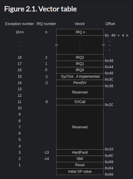
Interrupt priority levels
Microcontrollers allow interrupts to have priority levels. A higher-priority interrupt can preempt a lower-priority one. This ensures that time-critical events are handled first.
The NVIC: Interrupt Controller
The Nested Vectored Interrupt Controller (NVIC) is the hardware component in ARM Cortex-M processors that manages interrupts.
The NVIC is responsible for enabling and disabling individual interrupts, enforcing priority levels, and handling situations where multiple interrupts occur at once. When a higher-priority interrupt arrives, the NVIC can pause a lower-priority handler to deal with the more urgent event first.

Priority numbers in ARM Cortex-M work in reverse order: lower numbers mean higher priority. Among configurable interrupts, Priority 0 is the most urgent, while higher numbers like Priority 15 are less urgent. This means a Priority 0 interrupt can preempt a Priority 2 handler, but not the other way around.
Critical Sections
A critical section is a small sequence of code that must not be interrupted, in order to preserve the consistency of data or hardware state.
Consider a situation where the main code is updating a shared variable or configuring a peripheral using multiple steps. If an interrupt occurs in the middle of that sequence, and the interrupt handler accesses the same data or hardware, the system can end up in an inconsistent state.
In embedded systems, this is usually handled by temporarily disabling interrupts before entering the critical section and re-enabling them immediately after.
The goal is not to block interrupts for long periods of time, but to protect very small and sensitive pieces of code where consistency matters.
In the embedded Rust ecosystem, the critical-section crate provides a universal, portable API for entering critical sections across many platforms and environments. It defines functions like acquire, release, and with that libraries and applications can use to run code with interrupts disabled or otherwise protected.
Example:
#![allow(unused)]
fn main() {
use core::cell::Cell;
use critical_section::Mutex;
static MY_VALUE: Mutex<Cell<u32>> = Mutex::new(Cell::new(0));
critical_section::with(|cs| {
// This code runs within a critical section.
// `cs` is a token that you can use to "prove" that to some API,
// for example to a `Mutex`:
MY_VALUE.borrow(cs).set(42);
});
}Types of interrupts
In microcontrollers, interrupts usually come from a few common sources.
External interrupts
These are triggered by external signals, such as a button press or a change on a GPIO pin. They are often used for user input or reacting to external hardware events.
Timer interrupts
Timers can generate interrupts at fixed intervals. These are widely used for delays, scheduling tasks, blinking LEDs, or keeping time. Yup, we have actually been using timer interrupts already. Whenever we call Timer::after_millis(100).await in Embassy, that’s exactly what happens behind the scenes. The timer peripheral is configured to fire an interrupt after 100 milliseconds. Our task goes to sleep, and when the timer interrupt fires, it wakes the task back up. The CPU doesn’t sit there counting, it’s free to do other things or sleep while waiting.
Peripheral interrupts
Many peripherals can generate interrupts. For example:
- SPI and I2C peripherals can raise interrupts to signal transfer completion or error conditions.
- ADC peripherals can generate interrupts when a conversion finishes.
System exceptions
Some interrupts are generated by the processor itself, such as faults or system timers. These are usually reserved for system-level tasks.
Interrupts in the RP2350
In the previous chapter, we looked at what interrupts are and the role of the NVIC. Now, lets look at which interrupts are actually available on the RP2350.
Interrupts fall into two groups: system exceptions and external interrupts.
System exceptions are defined by the CPU architecture itself. These include reset, fault handlers, and the system timer. They behave the same way across most Cortex-M chips.
External interrupts come from peripherals on the RP2350. Each peripheral that can generate an interrupt has an IRQ number and a vector name. These are the names you will see in code.
The table below shows the external interrupts on the RP2350, numbered from 0 to 51. They cover common peripherals such as timers, GPIO, DMA, and communication interfaces like I2C, SPI, and UART.
You do not need to memorize this table. Its purpose is to help you recognize where names like I2C0_IRQ or UART0_IRQ come from when you see them in examples or documentation.
The full details are in the RP2350 datasheet, section 3.2 on page 82.
In the next chapter, we will see how Embassy uses these interrupts without requiring you to write interrupt handlers manually.
RP2350 External Interrupts
Important
Some interrupt descriptions are simplified here for a beginner-friendly overview. For more accurate and detailed information, refer to the RP2350 datasheet.
Timers
Timer alarms used for delays and scheduling.
| IRQ | Vector | Description |
|---|---|---|
| 0 | TIMER0_IRQ_0 | Timer 0 alarm interrupt |
| 1 | TIMER0_IRQ_1 | Timer 0 alarm interrupt |
| 2 | TIMER0_IRQ_2 | Timer 0 alarm interrupt |
| 3 | TIMER0_IRQ_3 | Timer 0 alarm interrupt |
| 4 | TIMER1_IRQ_0 | Timer 1 alarm interrupt |
| 5 | TIMER1_IRQ_1 | Timer 1 alarm interrupt |
| 6 | TIMER1_IRQ_2 | Timer 1 alarm interrupt |
| 7 | TIMER1_IRQ_3 | Timer 1 alarm interrupt |
PWM
PWM counter wrap events.
| IRQ | Vector | Description |
|---|---|---|
| 8 | PWM_IRQ_WRAP_0 | PWM wrap interrupt |
| 9 | PWM_IRQ_WRAP_1 | PWM wrap interrupt |
DMA
DMA transfer events.
| IRQ | Vector | Description |
|---|---|---|
| 10 | DMA_IRQ_0 | DMA transfer interrupt |
| 11 | DMA_IRQ_1 | DMA transfer interrupt |
| 12 | DMA_IRQ_2 | DMA transfer interrupt |
| 13 | DMA_IRQ_3 | DMA transfer interrupt |
USB
USB controller events.
| IRQ | Vector | Description |
|---|---|---|
| 14 | USBCTRL_IRQ | USB controller interrupt |
PIO
PIO state machine events.
| IRQ | Vector | Description |
|---|---|---|
| 15 | PIO0_IRQ_0 | PIO 0 interrupt |
| 16 | PIO0_IRQ_1 | PIO 0 interrupt |
| 17 | PIO1_IRQ_0 | PIO 1 interrupt |
| 18 | PIO1_IRQ_1 | PIO 1 interrupt |
| 19 | PIO2_IRQ_0 | PIO 2 interrupt |
| 20 | PIO2_IRQ_1 | PIO 2 interrupt |
GPIO and Core I/O
GPIO and core signaling events.
| IRQ | Vector | Description |
|---|---|---|
| 21 | IO_IRQ_BANK0 | GPIO interrupt |
| 22 | IO_IRQ_BANK0_NS | GPIO interrupt |
| 23 | IO_IRQ_QSPI | QSPI GPIO interrupt |
| 24 | IO_IRQ_QSPI_NS | QSPI GPIO interrupt |
| 25 | SIO_IRQ_FIFO | Inter-core FIFO interrupt |
| 26 | SIO_IRQ_BELL | Inter-core doorbell interrupt |
| 27 | SIO_IRQ_FIFO_NS | Inter-core FIFO interrupt |
| 28 | SIO_IRQ_BELL_NS | Inter-core doorbell interrupt |
| 29 | SIO_IRQ_MTIMECMP | System timer interrupt |
Communication Peripherals
Communication interface events.
| IRQ | Vector | Description |
|---|---|---|
| 30 | CLOCKS_IRQ | Clock system interrupt |
| 31 | SPI0_IRQ | SPI interrupt |
| 32 | SPI1_IRQ | SPI interrupt |
| 33 | UART0_IRQ | UART interrupt |
| 34 | UART1_IRQ | UART interrupt |
| 35 | ADC_IRQ_FIFO | ADC FIFO interrupt |
| 36 | I2C0_IRQ | I2C interrupt |
| 37 | I2C1_IRQ | I2C interrupt |
System and Power
System and power management events.
| IRQ | Vector | Description |
|---|---|---|
| 38 | OTP_IRQ | OTP interrupt |
| 39 | TRNG_IRQ | Random number generator interrupt |
| 40 | Reserved | Reserved |
| 41 | Reserved | Reserved |
| 42 | PLL_SYS_IRQ | System PLL interrupt |
| 43 | PLL_USB_IRQ | USB PLL interrupt |
| 44 | POWMAN_IRQ_POW | Power manager interrupt |
| 45 | POWMAN_IRQ_TIMER | Power manager timer interrupt |
Software IRQs
Interrupts that can be triggered by software.
| IRQ | Vector | Description |
|---|---|---|
| 46 | SPAREIRQ_IRQ_0 | Software interrupt |
| 47 | SPAREIRQ_IRQ_1 | Software interrupt |
| 48 | SPAREIRQ_IRQ_2 | Software interrupt |
| 49 | SPAREIRQ_IRQ_3 | Software interrupt |
| 50 | SPAREIRQ_IRQ_4 | Software interrupt |
| 51 | SPAREIRQ_IRQ_5 | Software interrupt |
C 实现
Using Interrupts with Embassy
In the previous chapter, we looked at what interrupts are and how the NVIC fits into the picture. Now lets see how interrupts are actually used in Embassy.
In Embassy, you normally do not write interrupt handlers yourself. Async drivers use interrupts internally to wait for hardware events and to wake tasks when those events happen. Your code just awaits an operation and continues when it is ready.
For some peripherals, Embassy needs a small amount of setup so it knows which hardware interrupt belongs to which driver. This is where bind_interrupts! comes in.
Why bind_interrupts! is Needed
Async peripherals like I2C, SPI do not finish their work in one step. While an operation is in progress, the task goes to sleep and the hardware generates interrupts as things move forward.
Embassy already provides the interrupt handlers for these peripherals. What it needs from you is the connection between the hardware interrupt and the handler it should use. The bind_interrupts! macro is how you make that connection.
You are not writing an interrupt handler here. You are just wiring things up so the async driver can work.
Binding an Interrupt for I2C
Here is a simple example for I2C:
#![allow(unused)]
fn main() {
use embassy_rp::{bind_interrupts, i2c};
use embassy_rp::peripherals::I2C0;
bind_interrupts!(struct Irqs {
I2C0_IRQ => i2c::InterruptHandler<I2C0>;
});
}This tells Embassy that the I2C0_IRQ interrupt should be handled by the I2C driver for I2C0. Once this is in place, async I2C operations can sleep and wake correctly.
Using Async I2C
After the interrupt is bound, using async I2C looks normal:
#![allow(unused)]
fn main() {
use embassy_rp::i2c::{I2c, Config as I2cConfig};
use embassy_rp::peripherals::I2C0;
let sda = p.PIN_16;
let scl = p.PIN_17;
let mut i2c = I2c::new_async(
p.I2C0,
scl,
sda,
Irqs,
I2cConfig::default(),
);
}When you later call an async operation like:
#![allow(unused)]
fn main() {
i2c.write(0x3C, &[0x00]).await;
}your task pauses and lets other code run. Meanwhile, the I2C hardware does its work. When the hardware finishes, an interrupt fires and Embassy wakes your task back up. The interrupt happens behind the scenes, you just see your code continue after the .await.
Inter-Integrated Circuit (I2C)
So far, we’ve been toggling output pins between High and Low states to control an LED and reading the same two levels from a button, but working with interesting devices like display modules, RFID readers, and SD card readers requires something more. Simple pin toggling won’t work here. We need a proper communication mechanism, and that’s where communication protocols come in. The most common ones are I2C, SPI, and UART. Each one has its own advantages and disadvantages.
Since we will be using an OLED display in the next chapter, and it communicates over I2C, this is the first protocol we are going to explore. OLED displays are one of the modules I enjoy the most. I’ve used them to make small games and a bunch of fun personal projects.
What Is I2C?
I2C stands for Inter-Integrated Circuit, also written as I²C. It’s one of the popular communication methods used by microcontrollers to talk to sensors, displays (like OLEDs), and other chips. It is a serial, half-duplex, and synchronous interface. Let’s break down what that means.
-
Serial means data is transferred one bit at a time, in sequence. Each bit is sent individually rather than sending multiple bits at once. These bits are carried over a data signal during communication.
-
Half duplex means data travels in only one direction at a time. A device either sends data or receives data, but not both at the same time. The direction switches as needed during communication.
-
Synchronous means both devices rely on a shared clock signal. This clock defines exactly when each bit of data is sent and read, keeping both devices aligned during communication.
Controller and Target
I2C uses a controller-target model. The controller (formerly known as master) is the device that initiates communication and provides the clock signal. The target (formerly known as slave) responds to the controller’s commands.

Figure: Single Controller and Single Target
In typical embedded projects, the microcontroller (e.g: Pico) acts as the controller, and connected devices like displays (e.g: OLED) or sensors act as targets.
I2C makes it easy to connect many devices on the same two wires. You can connect multiple targets to a single controller, which is the most common setup. I2C also supports multiple controllers on the same bus, so more than one controller can talk to one or more targets.
I2C Bus
The I2C bus uses just two lines, which are shared by all connected devices:
-
SCL (Serial Clock Line): Carries the clock signal from the controller. Sometimes devices label them as SCK.
-
SDA (Serial Data Line): Transfers the data in both directions. Sometimes devices label them as SDI.

Figure: Single Controller and Multiple Target
All connected devices share the same two wires. The controller selects which target to communicate with by sending that device’s unique address.
I2C Addresses
Each I2C target device has a 7-bit or 10-bit address. The most common is 7-bit, which allows for up to 128 possible addresses.
Many devices have a fixed address defined by the manufacturer, but others allow configuring the lower bits of the address using pins or jumpers. For example, a sensor might use pins labeled A0 and A1 to change its address, allowing you to use multiple copies of the same chip on the same bus.
When the controller wants to talk to a target, it starts by sending a START condition, followed by the device address and a read/write bit. The matching device responds with an ACK (acknowledge) signal, and communication continues.
Speed Modes
I2C supports different speed modes depending on how fast data needs to be transferred. Standard mode goes up to 100 kbps, fast mode reaches 400 kbps, and Fast Mode Plus allows up to 1 Mbps. For even faster communication, High-Speed mode supports up to 3.4 Mbps. There is also an Ultra-Fast mode (5 Mbps). The speed you can use depends on what speed modes are supported by both the microcontroller’s I2C interface and the connected target devices.
Why I2C?
I2C is ideal when you want to connect several devices using just two wires. It is well-suited for applications where speed is not critical but wiring simplicity is important.
The good news is that in Embedded Rust, you don’t need to implement the I2C protocol yourself. The embedded-hal crate defines common I2C traits, and the HAL for your chip takes care of the low-level details. In the next section, we will see more on it.
Resources
- Basics of the I2C Communication Protocol: Refer this if you want in-depth understanding how the controller communicates with target.
Raspberry Pi Pico 2(RP2350)’s I2C
Now that you understand the basics of the I2C protocol, let us look at how it works on the Raspberry Pi Pico 2. The RP2350 has two separate I2C controllers, named I2C0 and I2C1. Think of these as two independent communication channels that can operate simultaneously. This helps when two devices share the same I2C address, because you can place them on separate controllers.
Available I2C Pins
Both I2C controllers support multiple pin options for SDA and SCL. You only choose one pair for each controller.
| I2C Controller | GPIO Pins |
|---|---|
| I2C0 - SDA | GP0, GP4, GP8, GP12, GP16, GP20 |
| I2C0 - SCL | GP1, GP5, GP9, GP13, GP17, GP21 |
| I2C1 - SDA | GP2, GP6, GP10, GP14, GP18, GP26 |
| I2C1 - SCL | GP3, GP7, GP11, GP15, GP19, GP27 |

On the Pico 2 board layout, pins that support I2C functionality are labeled with SDA and SCL, and are also highlighted in blue to make them easy to identify.
Speed Options
The RP2350’s I2C controllers support three different speed modes, allowing you to match the capabilities of whatever devices you’re connecting:
- Standard mode: Up to 100 kb/s (kilobits per second) - the slowest but most universally compatible
- Fast mode: Up to 400 kb/s - a good balance for most sensors and displays
- Fast mode plus: Up to 1000 kb/s - for when you need quicker data transfer
It’s worth noting that the RP2350 doesn’t support the ultra-high-speed modes (High-speed at 3.4 Mb/s or Ultra-Fast at 5 Mb/s) that some specialized devices use. However, most common sensors, displays, and peripherals work perfectly fine within the supported speed ranges.
Controller or Target mode
The RP2350 can only be a Controller (master) or a Target (slave) at any given time—not both simultaneously on the same controller. For typical projects where the Pico 2 is controlling sensors and displays, you’ll always use controller mode.
For the complete technical specifications, you can refer to page 983 of the RP2350 Datasheet.
C 实现
Using I2C with the Embedded Rust Ecosystem
In the previous section, we learned the basics of I2C communication and how the controller-target (master-slave) model works. Now, let’s see how these concepts apply in the Embedded Rust ecosystem, where modular and reusable design is a key principle.
The Role of embedded-hal
The embedded-hal crate defines a standard set of traits for embedded hardware abstraction, including I2C. These traits allow driver code (like for displays or sensors) to be written generically so that it can run on many different microcontrollers without needing platform-specific changes.
The core I2C trait looks like this:
#![allow(unused)]
fn main() {
pub trait I2c<A: AddressMode = SevenBitAddress>: ErrorType {
// This method must be implemented by HAL authors
fn transaction(...);
// These are default methods built on top of `transaction`
fn read(...);
fn write(...);
fn write_read(...);
}
}The only method that the HAL is required to implement is transaction. The trait provides default implementations of read, write, and write_read using this method.
The generic type parameter A specifies the address mode and has a default type parameter of SevenBitAddress. So, in most cases you don’t need to specify it manually. For 10-bit addressing, you can use TenBitAddress instead.
Microcontroller-specific HAL crates (like esp-hal, stm32-hal, or nrf-hal) implement this trait for their I2C peripherals. For example, the esp-hal crate implements I2C. If you are curious, you can look at the implementation.
In addition to the regular
embedded-halcrate, there is anasyncversion calledembedded-hal-async. It defines similar traits, but they are designed to work withasynccode, which is useful when writing non-blocking drivers or tasks in embedded systems.
Platform-Independent Drivers
Imagine you are writing a driver for a sensor or a display that communicates over I2C. You don’t want to tie your code to a specific microcontroller like the Raspberry Pi Pico or ESP32. Instead, you can write the driver in a generic way using the embedded-hal trait.
As long as your driver only depends on the I2C trait, it can run on any platform that provides an implementation of this trait-such as STM32, nRF, or ESP32.
Sharing the I2C Bus
Many embedded projects connect multiple I2C devices (like an OLED display, an LCD, and various sensors) to the same SDA and SCL lines. However, only one device can control the bus at a time.

Figure: Microcontroller(Pico) and Multiple Devices
If you give exclusive access to one driver, other devices cannot communicate. This is where the embedded-hal-bus crate helps.
It provides wrapper types like AtomicDevice, CriticalSectionDevice, and RefCellDevice that allow multiple drivers to safely share access to the same I2C bus. These wrappers themselves implement the I2c trait, so drivers can use them as if they were the original bus.
You can use I2C in two ways:

-
Without sharing: If your application only talks to one I2C device, you can pass the I2C bus instance provided by the HAL (which implements the
I2ctrait) directly to the driver. -
With sharing: If your application needs to communicate with multiple I2C devices on the same bus, you can wrap the I2C bus instance (provided by the HAL) using one of the sharing types from the
embedded-hal-buscrate, such asAtomicDeviceorCriticalSectionDevice. This allows safe, coordinated access across multiple drivers.
Resources
- embedded-hal docs on I2C: This documentation provides in-depth details on how I2C traits are structured and how they are intended to be used across different platforms.
I2C in Embassy RP
Let’s see how to initialize and use I2C with Embassy on the Raspberry Pi Pico 2.
Blocking mode
Embassy provides a simple way to set up I2C in blocking mode:
#![allow(unused)]
fn main() {
let sda = p.PIN_16;
let scl = p.PIN_17;
info!("set up i2c");
let mut i2c = i2c::I2c::new_blocking(p.I2C0, scl, sda, Config::default());
}We use the new_blocking method to create an I2C instance that waits for each operation to finish before continuing. First we choose which I2C peripheral we want to work with, either I2C0 or I2C1. Once we select the peripheral, we must pair it with the correct GPIO pins for SCL and SDA.
For the configuration, the default implementation gives us standard 100 kHz communication and also enables internal pullups.
Customizing Config
The Config struct lets us control how the I2C bus behaves. We can adjust the communication speed and whether the internal pullups on the SDA and SCL lines are enabled.
If we want to increase the bus speed, we can change the frequency field:
#![allow(unused)]
fn main() {
let mut config = Config::default();
config.frequency = 400_000;
}If our circuit already includes external pullup resistors, we can disable the internal ones:
#![allow(unused)]
fn main() {
let mut config = Config::default();
config.sda_pullup = false;
config.scl_pullup = false;
}Sending Data
Many I2C devices require us to send commands or configuration bytes. For example, imagine we are configuring a sensor and need to write two bytes to it:
#![allow(unused)]
fn main() {
const SENSOR_ADDR: u8 = 0x68;
let config_data = [0x6B, 0x00];
i2c.write(SENSOR_ADDR, &config_data)?;
}Here, we’re sending two bytes to the device at address 0x68. The first byte 0x6B typically tells the device which register we’re writing to, and 0x00 is the value we want to write. Different devices use this pattern differently, so you’ll need to check your device’s datasheet to know what bytes to send.
Reading from a Register
Most I2C devices store their data in registers. To read a specific register, we use write_read. Let’s say we want to read the temperature from a sensor:
#![allow(unused)]
fn main() {
const TEMP_REGISTER: u8 = 0x41;
let mut buffer = [0u8; 2];
i2c.write_read(SENSOR_ADDR, &[TEMP_REGISTER], &mut buffer)?;
}We first tell the device “I want to read from register 0x41” (the write part), then the device sends us back 2 bytes of temperature data (the read part). The write_read method does both operations in a single I2C transaction. After this, our buffer will contain the raw temperature bytes that we can then convert to an actual temperature value.
Reading Continuously
Some devices automatically advance their internal pointer and keep producing data. For these cases we can use a simple read:
#![allow(unused)]
fn main() {
let mut buffer = [0u8; 5];
i2c.read(SENSOR_ADDR, &mut buffer)?;
}This reads bytes starting from the device’s current internal position. It is less common than write_read, but useful for sensors that stream data continuously.
Using Async Mode
If we’re building a more complex application that needs to handle multiple things at once, we can use async mode. This lets our program do other work while waiting for I2C operations to complete:
#![allow(unused)]
fn main() {
bind_interrupts!(struct Irqs {
I2C0_IRQ => i2c::InterruptHandler<I2C0>;
});
let mut i2c = I2c::new_async(
p.I2C0,
scl,
sda,
Irqs,
I2cConfig::default(),
);
let mut buffer = [0u8; 2];
i2c.write_read(SENSOR_ADDR, &[TEMP_REGISTER], &mut buffer).await?;
}Target (Slave) mode
The Pico can also act as an I2C target device (also known as a slave device), where it responds to requests from another controller. However, for most of our projects in this book, we’ll be using the Pico as the controller that talks to sensors and other peripherals, so we won’t cover target mode here.
OLED Display
In this section, we’ll learn how to connect an OLED display module to the Raspberry Pi Pico 2. OLED displays are one of the most fun components to work with because they open up so many creative possibilities. You can build games, create dashboards, or display sensor readings in a visual way.

To give you an idea of what is possible, I have built a few games using an OLED display. One of them is Pico Rex, a tiny dinosaur jumping game inspired by Chrome’s offline dino. You can check it out its GitHub project.
I have also made a small flappy-style game and a shooter game (along with other examples).
As you learn how to use the display, feel free to experiment and build your own ideas. Even simple animations or text updates can be surprisingly fun to create.
In next few chapters, we’ll create simple projects like displaying text and an image (display Ferris 🦀 image) on the OLED. We’ll use the I2C protocol to connect the OLED display to the Pico.
Meet the Hardware
OLED, short for Organic Light-Emitting Diode, is a popular display module. These displays come in various sizes and can support different colors. They communicate using either the I²C or SPI protocol.
For this exercise, we’ll use a 0.96-inch OLED monochrome module with a resolution of 128 × 64. It operates at 3.3 V. We can communicate using I2C communication protocol.
Tip
Most of the time, OLED displays come with pin headers included but not soldered. Soldering is a valuable skill to learn, but it requires care and preparation. Before attempting it, watch plenty of tutorials and do your research. It may feel challenging at first, but with practice, it gets easier. If you’re not comfortable soldering yet, consider looking for a pre-soldered version of the display, though it may cost slightly more.
SSD1306
The SSD1306 is the integrated controller chip that powers many small OLED displays including the module we are going to use (0.96-inch 128x64 module). This controller handles the communication between the Pico and the OLED panel, enabling the display to show text, graphics, and more.
DataSheet: datasheet for SSD1306.
How OLED module works?
We won’t dive into the details of how OLED technology works; instead, we’ll focus on what’s relevant for our exercises. The module has a resolution of 128 × 64, giving it a total of 128 × 64 = 8192 pixels. Each pixel can be turned on or off independently.
Don’t worry if these concepts are unclear for now - you can always research them later. These details are more relevant if you plan to write your own driver for the SSD1306 or work on more advanced tasks. For now, we already have a good crates that handles these aspects and simplifies the process.
In the datasheet, the 128 columns are referred to as segments, while the 64 rows are called commons (be careful not to confuse “commons” with “columns” due to their similar spelling).
Memory
The OLED display’s pixels are arranged in a page structure within GDDRAM (Graphics Display DRAM). GDDRAM is divided into 8 pages (From Page 0 to Page 7), each consisting of 128 columns (segments) and 8 rows (commons).
 (This image is taken from the datasheet)
A segment is 8 bits of data (one byte), with each bit representing a single pixel. When writing data, you will write an entire segment, meaning the entire byte is written at once.
 (This image is taken from the datasheet)
We can re-map both segments and commons through software for mechanical flexibility. You can find more details on page 25 of the SSD1306 datasheet.
Pages and Segments
I created an image to show how 128 × 64 pixels are divided into 8 pages. I then focused on a single page, which contains 128 segments (columns) and 8 rows. Finally, I zoomed in on a single segment to demonstrate how it represents 8 vertically stacked pixels, with each pixel corresponding to one bit.
![]()
Circuit
The OLED display requires four connections to the Raspberry Pi Pico. This example uses I2C0 with GPIO 16 and 17, but you can use any valid I2C pin pair on your Pico.
| Pico Pin | Wire | OLED Pin |
|---|---|---|
| GPIO 16 |
|
SDA |
| GPIO 17 |
|
SCL |
| 3.3 V |
|
VCC |
| GND |
|
GND |

Crates You Will Use
Now that you understand what the SSD1306 is and how I2C communication works, let’s explore how we actually draw graphics on the display. You might wonder if you need to send raw commands for every pixel. The good news is that you do not. The Rust ecosystem provides us with great tools that make this much easier.
Drawing on the Display
When working with the SSD1306 display in Rust, you’ll use two main crates that work together:
embedded-graphics- A drawing library that lets you create shapes, text, and imagesssd1306- A driver that controls the actual hardware

What is embedded-graphics?
embedded-graphics is a lightweight 2D drawing library made for memory limited embedded systems. Instead of setting individual pixels yourself, you use high level drawing commands. For example:
#![allow(unused)]
fn main() {
Circle::new(Point::new(20, 20), 30)
.into_styled(PrimitiveStyle::with_stroke(BinaryColor::On, 1))
.draw(&mut display)?; // display implements DrawTarget
}This draws a circle without you needing to calculate any pixel positions or understand how the display stores its data internally.
What embedded-graphics provides:
- Drawing primitives such as circles, rectangles, lines, and triangles
- Text rendering - display text with different fonts
- Image and icon support through compatible image crates
- Style options for color, stroke width, and fill
The Key Design Principle
embedded-graphics is completely display-independent. It doesn’t know anything about your specific hardware (whether it’s an SSD1306, ST7789, or any other display). It simply knows how to describe what should be drawn. The actual display driver then handles the hardware-specific details of turning those instructions into real pixels.
This design means you can write drawing code once and use it with many different displays, just by changing the driver.
You can explore more in the official documentation: https://docs.rs/embedded-graphics/latest/embedded_graphics/
What is the ssd1306 Crate?
The ssd1306 crate is a hardware driver for displays that use the SSD1306 controller chip. It handles all the low-level work needed to communicate with your display. This includes initializing the screen, sending the correct I2C or SPI commands, managing an internal buffer when required, and updating the pixels on the hardware.
Graphics Mode
The ssd1306 driver supports multiple modes, but for drawing graphics, you’ll use BufferedGraphicsMode. You enter this mode by calling:
#![allow(unused)]
fn main() {
let display = ssd1306::Ssd1306::new(i2c, size, rotation)
.into_buffered_graphics_mode();
}In this mode, the driver maintains an internal buffer in RAM and implements the DrawTarget trait from embedded-graphics-core. This is what allows the two crates to work together.
How They Work Together: The DrawTarget Trait
If you are here, you probably already understand Rust traits. A trait basically describes what something can do, and the implementation decides how it actually does it.
DrawTarget is the trait that allows embedded-graphics to send drawing commands to a display driver. When the ssd1306 driver implements this trait, it is essentially saying:
“I can accept the pixels that embedded graphics produces, and I know how to put those pixels onto an SSD1306 screen.”
Here is what actually happens when you draw something:
- You create shapes, text, or images using embedded-graphics primitives.
- You call
.draw(&mut display)to render them. embedded-graphicsgenerates the pixels that need to be drawn.- The
ssd1306driver takes those pixels and stores them in its internal buffer. - When you call
display.flush(), the driver sends the updated pixels to the OLED hardware.
Here’s a simple example:
#![allow(unused)]
fn main() {
// Create a circle using embedded-graphics
let circle = Circle::new(Point::new(64, 32), 20)
.into_styled(PrimitiveStyle::with_fill(BinaryColor::On));
// Draw it onto the display driver
circle.draw(&mut display)?; // Write pixel data into the driver's buffer
display.flush()?; // Send buffer to the actual screen
}Async mode
The ssd1306 crate also supports async operation when you enable the async feature. This is useful if you’re using Embassy.
To use async mode, add the feature to your Cargo.toml:
ssd1306 = { version = "0.10.0", features = ["async"] }
When the async feature is enabled, the driver uses embedded-hal-async traits instead of the regular blocking embedded-hal traits. This allows the I2C/SPI communication to happen asynchronously, which is helpful when you want to do other tasks while waiting for display updates.
The main difference is that methods like .init() and .flush() become async and need to be .awaited:
#![allow(unused)]
fn main() {
// Async version
let mut display = Ssd1306Async::new(interface, DisplaySize128x64, DisplayRotation::Rotate0)
.into_buffered_graphics_mode();
display.init().await?; // Note the .await
// Drawing still works the same way
circle.draw(&mut display)?;
display.flush().await?; // This is now async too
}C 实现
Hello OLED
We are going to keep things simple. We will just display “Hello, Rust!” on the OLED display. We will first use Embassy, then we will do the same using rp-hal.
Create Project
As usual, generate the project from the template with cargo-generate:
cargo generate --git https://github.com/ImplFerris/pico2-template.git --tag v0.3.2
When prompted, give your project a name like “hello-oled” and choose “embassy” as the HAL. Enable defmt logging, if you have a debug probe so you can view logs also.
Update Dependencies
Add the following lines to your Cargo.toml under dependencies:
embedded-graphics = "0.8.1"
ssd1306 = { version = "0.10.0", features = ["async"] }
We will enable the async feature so the ssd1306 driver can be used with Embassy async I2C. You can also use it without this feature and use Embassy I2C in blocking mode.
Additional imports
Add these imports at the top of your main.rs:
#![allow(unused)]
fn main() {
// Interrupt Binding
use embassy_rp::peripherals::I2C0;
use embassy_rp::{bind_interrupts, i2c};
// I2C
use embassy_rp::i2c::{Config as I2cConfig, I2c};
// OLED
use ssd1306::{I2CDisplayInterface, Ssd1306Async, prelude::*};
// Embedded Graphics
use embedded_graphics::{
mono_font::{MonoTextStyleBuilder, ascii::FONT_6X10},
pixelcolor::BinaryColor,
prelude::Point,
prelude::*,
text::{Baseline, Text},
};
}Bind I2C Interrupt
We discussed this in detail in the interrupts section, so you should already be familiar with what it does. This binds the I2C0_IRQ interrupt to the Embassy I2C interrupt handler for I2C0.
#![allow(unused)]
fn main() {
bind_interrupts!(struct Irqs {
I2C0_IRQ => i2c::InterruptHandler<I2C0>;
});
}Initialize I2C
First, we need to set up the I2C bus to communicate with the display.
#![allow(unused)]
fn main() {
let sda = p.PIN_16;
let scl = p.PIN_17;
let mut i2c_config = I2cConfig::default();
i2c_config.frequency = 400_000; //400kHz
let i2c_bus = I2c::new_async(p.I2C0, scl, sda, Irqs, i2c_config);
}We have connected the OLED’s SDA line to Pin 16 and the SCL line to Pin 17. Throughout this chapter we will keep using these same pins. If you have connected your display to a different valid I2C pair, adjust the code to match your wiring.
We are using the new_async method to create an I2C instance in async mode. This allows I2C transfers to await instead of blocking the CPU. We use a 400 kHz bus speed, which is commonly supported by SSD1306 displays.
Initialize Display
Now we create the display interface and initialize it:
#![allow(unused)]
fn main() {
let i2c_interface = I2CDisplayInterface::new(i2c_bus);
let mut display = Ssd1306Async::new(i2c_interface, DisplaySize128x64, DisplayRotation::Rotate0)
.into_buffered_graphics_mode();
}I2CDisplayInterface::new(i2c_bus) wraps the async I2C bus so it can be used by the SSD1306 driver. It uses the default I2C address 0x3C, which is standard for most SSD1306 modules.
We create the display instance by specifying a 128x64 display and the default orientation. We also enable buffered graphics mode so we can draw into a RAM buffer using embedded-graphics.
#![allow(unused)]
fn main() {
display
.init()
.await
.expect("failed to initialize the display");
}Finally, display.init() sends initialization commands to the display hardware. This wakes up the display and configures it properly.
Writing Text
Before we can draw text, we need to define how the text should look:
#![allow(unused)]
fn main() {
let text_style = MonoTextStyleBuilder::new()
.font(&FONT_6X10)
.text_color(BinaryColor::On)
.build();
}This creates a text style using FONT_6X10, a built-in monospaced font that’s 6 pixels wide and 10 pixels tall. We set BinaryColor::On to display white pixels on our black background since the OLED is monochrome.
Now let’s draw the text to the display’s buffer:
#![allow(unused)]
fn main() {
defmt::info!("sending text to display");
Text::with_baseline("Hello, Rust!", Point::new(0, 16), text_style, Baseline::Top)
.draw(&mut display)
.expect("failed to draw text to display");
}We’re rendering “Hello, Rust!” at position (0, 16), which is 16 pixels down from the top of the screen. We use the text style we defined earlier and align the text using its top edge with Baseline::Top.
The .draw(&mut display) call renders the text into the display’s internal buffer. At this point, the text exists in RAM but is not yet visible on the physical screen.
Displaying Text
Finally, we send the buffer contents to the actual OLED hardware:
#![allow(unused)]
fn main() {
display
.flush()
.await
.expect("failed to flush data to display");
}This is when the I2C communication happens. The driver sends the bytes from RAM to the display controller, and you’ll see “Hello, Rust!” appear on your OLED screen!
Complete Code
Here’s everything put together:
#![no_std]
#![no_main]
use embassy_executor::Spawner;
use embassy_rp as hal;
use embassy_rp::block::ImageDef;
use embassy_time::Timer;
//Panic Handler
use panic_probe as _;
// Defmt Logging
use defmt_rtt as _;
// Interrupt Binding
use embassy_rp::peripherals::I2C0;
use embassy_rp::{bind_interrupts, i2c};
// I2C
use embassy_rp::i2c::{Config as I2cConfig, I2c};
// OLED
use ssd1306::{I2CDisplayInterface, Ssd1306Async, prelude::*};
// Embedded Graphics
use embedded_graphics::{
mono_font::{MonoTextStyleBuilder, ascii::FONT_6X10},
pixelcolor::BinaryColor,
prelude::Point,
prelude::*,
text::{Baseline, Text},
};
/// Tell the Boot ROM about our application
#[unsafe(link_section = ".start_block")]
#[used]
pub static IMAGE_DEF: ImageDef = hal::block::ImageDef::secure_exe();
bind_interrupts!(struct Irqs {
I2C0_IRQ => i2c::InterruptHandler<I2C0>;
});
#[embassy_executor::main]
async fn main(_spawner: Spawner) {
let p = embassy_rp::init(Default::default());
let sda = p.PIN_16;
let scl = p.PIN_17;
let mut i2c_config = I2cConfig::default();
i2c_config.frequency = 400_000; //400kHz
let i2c_bus = I2c::new_async(p.I2C0, scl, sda, Irqs, i2c_config);
let i2c_interface = I2CDisplayInterface::new(i2c_bus);
let mut display = Ssd1306Async::new(i2c_interface, DisplaySize128x64, DisplayRotation::Rotate0)
.into_buffered_graphics_mode();
display
.init()
.await
.expect("failed to initialize the display");
let text_style = MonoTextStyleBuilder::new()
.font(&FONT_6X10)
.text_color(BinaryColor::On)
.build();
defmt::info!("sending text to display");
Text::with_baseline("Hello, Rust!", Point::new(0, 16), text_style, Baseline::Top)
.draw(&mut display)
.expect("failed to draw text to display");
display
.flush()
.await
.expect("failed to flush data to display");
loop {
Timer::after_millis(100).await;
}
}
// Program metadata for `picotool info`.
// This isn't needed, but it's recomended to have these minimal entries.
#[unsafe(link_section = ".bi_entries")]
#[used]
pub static PICOTOOL_ENTRIES: [embassy_rp::binary_info::EntryAddr; 4] = [
embassy_rp::binary_info::rp_program_name!(c"hello-oled"),
embassy_rp::binary_info::rp_program_description!(c"Hello OLED"),
embassy_rp::binary_info::rp_cargo_version!(),
embassy_rp::binary_info::rp_program_build_attribute!(),
];
// End of fileClone the existing project
You can clone (or refer) project I created and navigate to the hello-oled folder.
git clone https://github.com/ImplFerris/pico2-embassy-projects
cd pico2-embassy-projects/oled/hello-oled
Hello Rust on OLED
The same hello world we will do with rp-hal also.
Generating From template
To generate the project, run:
cargo generate --git https://github.com/ImplFerris/pico2-template.git --tag v0.3.2
When prompted, choose a name for your project-let’s go with “oh-led”. Don’t forget to select rp-hal as the HAL.
Then, navigate into the project folder:
cd PROJECT_NAME
# For example, if you named your project "oh-led":
# cd oh-led
Add Additional Dependencies
Since we are using the SSD1306 OLED display, we need to include the SSD1306 driver. To add this dependency, use the following Cargo command:
cargo add ssd1306@0.10.0
We will use the embedded_graphics crate to handle graphical rendering on the OLED display, to draw images, shapes, and text.
cargo add embedded-graphics@0.8.1
Additional imports
In addition to the imports from the template, you’ll need the following additional dependencies for this task.
#![allow(unused)]
fn main() {
// Embedded Graphics
use embedded_graphics::mono_font::MonoTextStyleBuilder;
use embedded_graphics::mono_font::ascii::FONT_6X10;
use embedded_graphics::pixelcolor::BinaryColor;
use embedded_graphics::prelude::*;
use embedded_graphics::text::{Baseline, Text};
// For setting the Frequency
use hal::fugit::RateExtU32;
use hal::gpio::{FunctionI2C, Pin};
// SSD1306 Display
use ssd1306::{I2CDisplayInterface, Ssd1306, prelude::*};
}Pin Configuration
We start by configuring the GPIO pins for the I2C communication. In this case, GPIO18 is set as the SDA pin, and GPIO19 is set as the SCL pin. We then configure the I2C peripheral to work in controller mode.
#![allow(unused)]
fn main() {
// Configure two pins as being I²C, not GPIO
let sda_pin: Pin<_, FunctionI2C, _> = pins.gpio16.reconfigure();
let scl_pin: Pin<_, FunctionI2C, _> = pins.gpio17.reconfigure();
// Create the I²C drive, using the two pre-configured pins. This will fail
// at compile time if the pins are in the wrong mode, or if this I²C
// peripheral isn't available on these pins!
let i2c = hal::I2C::i2c0(
pac.I2C0,
sda_pin,
scl_pin,
400.kHz(),
&mut pac.RESETS,
&clocks.system_clock,
);
}Prepare Display
We create an interface for the OLED display using the I2C.
#![allow(unused)]
fn main() {
//helper struct is provided by the ssd1306 crate
let interface = I2CDisplayInterface::new(i2c);
// initialize the display
let mut display = Ssd1306::new(interface, DisplaySize128x64, DisplayRotation::Rotate0)
.into_buffered_graphics_mode();
display.init().expect("failed to initialize the display");
}Set Text Style and Draw
Next, we define the text style and use it to display “Hello Rust” on the screen:
#![allow(unused)]
fn main() {
// Embedded graphics
let text_style = MonoTextStyleBuilder::new()
.font(&FONT_6X10)
.text_color(BinaryColor::On)
.build();
Text::with_baseline(
"Hello, Rusty!",
Point::new(0, 16),
text_style,
Baseline::Top,
)
.draw(&mut display)
.expect("failed to draw text to display");
}Here, we are writing the message at coordinates (x=0, y=16).
Write out data to a display
#![allow(unused)]
fn main() {
display.flush().expect("failed to flush data to display");
}Complete code
#![no_std]
#![no_main]
use embedded_hal::delay::DelayNs;
use hal::block::ImageDef;
use rp235x_hal as hal;
//Panic Handler
use panic_probe as _;
// Defmt Logging
use defmt_rtt as _;
// Embedded Graphics
use embedded_graphics::mono_font::MonoTextStyleBuilder;
use embedded_graphics::mono_font::ascii::FONT_6X10;
use embedded_graphics::pixelcolor::BinaryColor;
use embedded_graphics::prelude::*;
use embedded_graphics::text::{Baseline, Text};
// For setting the Frequency
use hal::fugit::RateExtU32;
use hal::gpio::{FunctionI2C, Pin};
// SSD1306 Display
use ssd1306::{I2CDisplayInterface, Ssd1306, prelude::*};
/// Tell the Boot ROM about our application
#[unsafe(link_section = ".start_block")]
#[used]
pub static IMAGE_DEF: ImageDef = hal::block::ImageDef::secure_exe();
/// External high-speed crystal on the Raspberry Pi Pico 2 board is 12 MHz.
/// Adjust if your board has a different frequency
const XTAL_FREQ_HZ: u32 = 12_000_000u32;
#[hal::entry]
fn main() -> ! {
// Grab our singleton objects
let mut pac = hal::pac::Peripherals::take().unwrap();
// Set up the watchdog driver - needed by the clock setup code
let mut watchdog = hal::Watchdog::new(pac.WATCHDOG);
// Configure the clocks
//
// The default is to generate a 125 MHz system clock
let clocks = hal::clocks::init_clocks_and_plls(
XTAL_FREQ_HZ,
pac.XOSC,
pac.CLOCKS,
pac.PLL_SYS,
pac.PLL_USB,
&mut pac.RESETS,
&mut watchdog,
)
.ok()
.unwrap();
// The single-cycle I/O block controls our GPIO pins
let sio = hal::Sio::new(pac.SIO);
// Set the pins up according to their function on this particular board
let pins = hal::gpio::Pins::new(
pac.IO_BANK0,
pac.PADS_BANK0,
sio.gpio_bank0,
&mut pac.RESETS,
);
let mut timer = hal::Timer::new_timer0(pac.TIMER0, &mut pac.RESETS, &clocks);
// Configure two pins as being I²C, not GPIO
let sda_pin: Pin<_, FunctionI2C, _> = pins.gpio18.reconfigure();
let scl_pin: Pin<_, FunctionI2C, _> = pins.gpio19.reconfigure();
// Create the I²C drive, using the two pre-configured pins. This will fail
// at compile time if the pins are in the wrong mode, or if this I²C
// peripheral isn't available on these pins!
let i2c = hal::I2C::i2c1(
pac.I2C1,
sda_pin,
scl_pin,
400.kHz(),
&mut pac.RESETS,
&clocks.system_clock,
);
//helper struct is provided by the ssd1306 crate
let interface = I2CDisplayInterface::new(i2c);
// initialize the display
let mut display = Ssd1306::new(interface, DisplaySize128x64, DisplayRotation::Rotate0)
.into_buffered_graphics_mode();
display.init().expect("failed to initialize the display");
// Embedded graphics
let text_style = MonoTextStyleBuilder::new()
.font(&FONT_6X10)
.text_color(BinaryColor::On)
.build();
Text::with_baseline(
"Hello, Rusty!",
Point::new(0, 16),
text_style,
Baseline::Top,
)
.draw(&mut display)
.expect("failed to draw text to display");
display.flush().expect("failed to flush data to display");
loop {
timer.delay_ms(100);
}
}
// Program metadata for `picotool info`.
// This isn't needed, but it's recomended to have these minimal entries.
#[unsafe(link_section = ".bi_entries")]
#[used]
pub static PICOTOOL_ENTRIES: [hal::binary_info::EntryAddr; 5] = [
hal::binary_info::rp_cargo_bin_name!(),
hal::binary_info::rp_cargo_version!(),
hal::binary_info::rp_program_description!(c"your program description"),
hal::binary_info::rp_cargo_homepage_url!(),
hal::binary_info::rp_program_build_attribute!(),
];
// End of fileClone the existing project
You can clone (or refer) project I created and navigate to the hello-oled folder.
git clone https://github.com/ImplFerris/pico2-rp-projects
cd pico2-projects/hello-oled
Draw Raw Image on OLED Display with Raspberry Pi Pico
In this exercise, we will draw a raw image using only byte arrays. We will create the Ohm (Ω) symbol in a 1BPP (1 Bit Per Pixel) format.
1BPP Image
The 1BPP (1 bit per pixel) format uses a single bit for each pixel. It can represent only two colors, typically black and white. If the bit value is 0, it will typically be full black. If the bit value is 1, it will typically be full white.
We will create the ohm symbol using an 8 × 5 pixel grid in 1bpp format. I have highlighted the 1’s in the byte array to show how they turn on the pixels to form the ohm symbol.

I chose 8 as the width to keep the example simple. This makes it easy to represent the 8 pixels width using a single byte (8 bits). But if you increase the width, it won’t fit in one byte anymore, so it will need to be spread across multiple elements in the byte array. I will explain this in later chapters. For now, let’s keep it simple.
Ohm symbol on the OLED Display (128x64)
Let me show you how it looks when the Ohm symbol is positioned on the OLED display (128 × 64 resolution) at position zero (x is 0 and y is also 0).

This is an enlarged illustration. When you see the symbol on the actual display module, it will be small.
Reference
- Embedded Graphics’ ImageRaw Documentation
- Image2Bytes: Convert image to Hex byte array
Drawing a Single Byte Image in Embedded Rust using embedded-graphics
By now, i hope you understand how the image is represented in the byte array. Now, let’s move on to the coding part.
Create Project
As usual, generate the project from the template with cargo-generate:
cargo generate --git https://github.com/ImplFerris/pico2-template.git --tag v0.3.2
When prompted, give your project a name like “byte-oled” and choose “embassy” as the HAL. Enable defmt logging, if you have a debug probe so you can view logs also.
Update Dependencies
Add the following lines to your Cargo.toml under dependencies:
embedded-graphics = "0.8.1"
ssd1306 = { version = "0.10.0", features = ["async"] }
Additional imports
Add these imports at the top of your main.rs:
#![allow(unused)]
fn main() {
// Interrupt Binding
use embassy_rp::peripherals::I2C0;
use embassy_rp::{bind_interrupts, i2c};
// I2C
use embassy_rp::i2c::{Config as I2cConfig, I2c};
// OLED
use ssd1306::{I2CDisplayInterface, Ssd1306Async, prelude::*};
// Embedded Graphics
use embedded_graphics::{
image::{Image, ImageRaw},
pixelcolor::BinaryColor,
prelude::Point,
prelude::*,
};
}Boilerplate codes
We have already explained this part in the previous chapter.
Bind I2C Interrupt
#![allow(unused)]
fn main() {
bind_interrupts!(struct Irqs {
I2C0_IRQ => i2c::InterruptHandler<I2C0>;
});
}Initialize I2C and Display instance
#![allow(unused)]
fn main() {
let sda = p.PIN_16;
let scl = p.PIN_17;
let mut i2c_config = I2cConfig::default();
i2c_config.frequency = 400_000; // 400kHz
let i2c_bus = I2c::new_async(p.I2C0, scl, sda, Irqs, i2c_config);
let i2c_interface = I2CDisplayInterface::new(i2c_bus);
let mut display = Ssd1306Async::new(i2c_interface, DisplaySize128x64, DisplayRotation::Rotate0)
.into_buffered_graphics_mode();
display
.init()
.await
.expect("failed to initialize the display");
}Create Your Image
We store our image as a byte array. Each byte represents one row of pixels.
#![allow(unused)]
fn main() {
// 8x5 pixels
#[rustfmt::skip]
const IMG_DATA: &[u8] = &[
0b00111000,
0b01000100,
0b01000100,
0b00101000,
0b11101110,
];
}This creates an Ohm symbol (Ω) that’s 8 pixels wide and 5 pixels tall. Each 0b means we’re writing in binary using 1s and 0s. A 1 means the pixel is ON (white), and a 0 means the pixel is OFF (black). Each line represents one row of the image from top to bottom.
Draw the Image
Now let’s put the image on the display:
#![allow(unused)]
fn main() {
let raw_image = ImageRaw::<BinaryColor>::new(IMG_DATA, 8);
let image = Image::new(&raw_image, Point::zero());
}The first line creates a raw image from our byte data. We tell it the image is 8 pixels wide, and it figures out the height by itself. The second line places the image at position (0, 0), which is the top-left corner of the screen.
Display the Image
Just like in the previous chapter, we need to draw the image to the display buffer and then send it to the screen:
#![allow(unused)]
fn main() {
image.draw(&mut display).expect("failed to draw text to display");
display.flush().await.expect("failed to flush data to display");
}Clone the existing project
You can also clone (or refer) project I created and navigate to the byte-oled folder.
git clone https://github.com/ImplFerris/pico2-embassy-projects
cd pico2-embassy-projects/oled/byte-oled
The Complete Code
#![no_std]
#![no_main]
use embassy_executor::Spawner;
use embassy_rp as hal;
use embassy_rp::block::ImageDef;
use embassy_time::Timer;
//Panic Handler
use panic_probe as _;
// Defmt Logging
use defmt_rtt as _;
// Interrupt Binding
use embassy_rp::peripherals::I2C0;
use embassy_rp::{bind_interrupts, i2c};
// I2C
use embassy_rp::i2c::{Config as I2cConfig, I2c};
// OLED
use ssd1306::{I2CDisplayInterface, Ssd1306Async, prelude::*};
// Embedded Graphics
use embedded_graphics::{
image::{Image, ImageRaw},
pixelcolor::BinaryColor,
prelude::Point,
prelude::*,
};
/// Tell the Boot ROM about our application
#[unsafe(link_section = ".start_block")]
#[used]
pub static IMAGE_DEF: ImageDef = hal::block::ImageDef::secure_exe();
bind_interrupts!(struct Irqs {
I2C0_IRQ => i2c::InterruptHandler<I2C0>;
});
// 8x5 pixels
#[rustfmt::skip]
const IMG_DATA: &[u8] = &[
0b00111000,
0b01000100,
0b01000100,
0b00101000,
0b11101110,
];
#[embassy_executor::main]
async fn main(_spawner: Spawner) {
let p = embassy_rp::init(Default::default());
let sda = p.PIN_16;
let scl = p.PIN_17;
let mut i2c_config = I2cConfig::default();
i2c_config.frequency = 400_000; // 400kHz
let i2c_bus = I2c::new_async(p.I2C0, scl, sda, Irqs, i2c_config);
let i2c_interface = I2CDisplayInterface::new(i2c_bus);
let mut display = Ssd1306Async::new(i2c_interface, DisplaySize128x64, DisplayRotation::Rotate0)
.into_buffered_graphics_mode();
display
.init()
.await
.expect("failed to initialize the display");
let raw_image = ImageRaw::<BinaryColor>::new(IMG_DATA, 8);
let image = Image::new(&raw_image, Point::zero());
image
.draw(&mut display)
.expect("failed to draw text to display");
display
.flush()
.await
.expect("failed to flush data to display");
loop {
Timer::after_millis(100).await;
}
}
// Program metadata for `picotool info`.
// This isn't needed, but it's recomended to have these minimal entries.
#[unsafe(link_section = ".bi_entries")]
#[used]
pub static PICOTOOL_ENTRIES: [embassy_rp::binary_info::EntryAddr; 4] = [
embassy_rp::binary_info::rp_program_name!(c"byte-oled"),
embassy_rp::binary_info::rp_program_description!(c"your program description"),
embassy_rp::binary_info::rp_cargo_version!(),
embassy_rp::binary_info::rp_program_build_attribute!(),
];
// End of fileUsing Multiple Bytes to Represent Wider Pixel Widths
In the previous example, we kept it simple by using an 8-pixel wide image. This made things easy because each row fit perfectly into a single byte. However, real images often need more pixels. So how do we represent them when one byte isn’t enough? The answer is simple: we use multiple bytes. But this creates a problem. If we’re using multiple bytes, how does the system know where one row ends and the next one begins?
This is exactly why we need to tell the embedded graphics crate the exact width of our image. When we specify the width, the system knows how many bytes to use for each row. Once it knows the width and the image format, it can figure out the height automatically.
Understanding the Math
Let’s look at an example with an image that’s 31 pixels wide and 7 pixels tall. The width is 31 pixels, and each pixel takes up 1 bit of space. To figure out how many bytes we need for each row, we do some simple math. Since a byte holds 8 bits, we divide 31 by 8. This gives us 3 complete bytes, which covers 24 pixels. But we still have 7 pixels left over, so we need one more byte to hold them. In total, we need 4 bytes to represent each row of 31 pixels. If the image has 7 rows then the total data length is 4 times 7, which is 28 bytes.

How the System Calculates Height
The embedded graphics crate uses code like this internally to calculate the height. You don’t need to add this to your own code. I’m showing it here just so you can see how it works behind the scenes:
#![allow(unused)]
fn main() {
let height = data.len() / bytes_per_row(width, C::Raw::BITS_PER_PIXEL);
//...
//...
const fn bytes_per_row(width: u32, bits_per_pixel: usize) -> usize {
(width as usize * bits_per_pixel + 7) / 8
}
}In our example, the data array has 28 entries, each pixel uses 1 bit, and the image width is 31. When you run this calculation, you get 4 bytes per row and a height of 7 pixels.
Try It Yourself
You can run this code right here or in the Rust Playground to see how the calculation works:
// 31x7 pixel
#[rustfmt::skip]
const IMG_DATA: &[u8] = &[
// 1st row
0b00000001,0b11111111,0b11111111,0b00000000,
// 2nd row
0b00000001,0b11111111,0b11111111,0b00000000,
//3rd row
0b00000001,0b10000000,0b00000011,0b00000000,
//4th row
0b11111111,0b10000000,0b00000011,0b11111110,
//5th row
0b00000001,0b10000000,0b00000011,0b00000000,
//6th row
0b00000001,0b11111111,0b11111111,0b00000000,
//7th row
0b00000001,0b11111111,0b11111111,0b00000000,
];
const fn bytes_per_row(width: u32, bits_per_pixel: usize) -> usize {
(width as usize * bits_per_pixel + 7) / 8
}
fn main(){
const BITS_PER_PIXEL: usize = 1;
let width = 31;
let data = IMG_DATA;
println!("Bytes Per Row:{}", bytes_per_row(width,BITS_PER_PIXEL));
let height = data.len() / bytes_per_row(width, BITS_PER_PIXEL);
println!("Height: {}", height);
}You dont need to manually create these byte array, you can use an online tool like imag2bytes to generate the byte array for you.
多字节代码
Drawing a Multi-Byte Image in Embedded Rust using embedded-graphics
Now let’s write the code to display a wider image on our OLED screen. The main changes from the previous example are the image data and the width value. This time, we’ll display a resistor symbol in the IEC-60617 style.
Project base
We will copy the byte-oled project and work on top of that.
git clone https://github.com/ImplFerris/pico2-embassy-projects
cp -r pico2-embassy-projects/oled/byte-oled ~/YOUR_PROJECT_FOLDER/oled-rawimg
or you can simply create a fresh project from the template and follow the same steps we used earlier.
Image Data
Here’s the byte array for the resistor symbol. Notice how each row needs multiple bytes because the image is 31 pixels wide.
#![allow(unused)]
fn main() {
// 31x7 pixel
#[rustfmt::skip]
const IMG_DATA: &[u8] = &[
// 1st row
0b00000001,0b11111111,0b11111111,0b00000000,
// 2nd row
0b00000001,0b11111111,0b11111111,0b00000000,
//3rd row
0b00000001,0b10000000,0b00000011,0b00000000,
//4th row
0b11111111,0b10000000,0b00000011,0b11111110,
//5th row
0b00000001,0b10000000,0b00000011,0b00000000,
//6th row
0b00000001,0b11111111,0b11111111,0b00000000,
//7th row
0b00000001,0b11111111,0b11111111,0b00000000,
];
}Creating and Positioning the Image
We need to set the width to 31 pixels. We’ll draw the image at position (x=35, y=35). There’s no special reason for these coordinates. I just wanted to show you that you can place images anywhere on the screen, not just at point zero. Feel free to try different position values and see what happens.
#![allow(unused)]
fn main() {
let raw_image = ImageRaw::<BinaryColor>::new(IMG_DATA, 31);
let image = Image::new(&raw_image, Point::new(35, 35));
}Clone the existing project
You can also clone (or refer) project I created and navigate to the oled-rawimg folder.
git clone https://github.com/ImplFerris/pico2-embassy-projects
cd pico2-embassy-projects/oled/oled-rawimg
The full code
#![no_std]
#![no_main]
use embassy_executor::Spawner;
use embassy_rp as hal;
use embassy_rp::block::ImageDef;
use embassy_time::Timer;
//Panic Handler
use panic_probe as _;
// Defmt Logging
use defmt_rtt as _;
// Interrupt Binding
use embassy_rp::peripherals::I2C0;
use embassy_rp::{bind_interrupts, i2c};
// I2C
use embassy_rp::i2c::{Config as I2cConfig, I2c};
// OLED
use ssd1306::{I2CDisplayInterface, Ssd1306Async, prelude::*};
// Embedded Graphics
use embedded_graphics::{
image::{Image, ImageRaw},
pixelcolor::BinaryColor,
prelude::Point,
prelude::*,
};
/// Tell the Boot ROM about our application
#[unsafe(link_section = ".start_block")]
#[used]
pub static IMAGE_DEF: ImageDef = hal::block::ImageDef::secure_exe();
bind_interrupts!(struct Irqs {
I2C0_IRQ => i2c::InterruptHandler<I2C0>;
});
// 31x7 pixel
#[rustfmt::skip]
const IMG_DATA: &[u8] = &[
// 1st row
0b00000001,0b11111111,0b11111111,0b00000000,
// 2nd row
0b00000001,0b11111111,0b11111111,0b00000000,
//3rd row
0b00000001,0b10000000,0b00000011,0b00000000,
//4th row
0b11111111,0b10000000,0b00000011,0b11111110,
//5th row
0b00000001,0b10000000,0b00000011,0b00000000,
//6th row
0b00000001,0b11111111,0b11111111,0b00000000,
//7th row
0b00000001,0b11111111,0b11111111,0b00000000,
];
#[embassy_executor::main]
async fn main(_spawner: Spawner) {
let p = embassy_rp::init(Default::default());
let sda = p.PIN_16;
let scl = p.PIN_17;
let mut i2c_config = I2cConfig::default();
i2c_config.frequency = 400_000; // 400kHz
let i2c_bus = I2c::new_async(p.I2C0, scl, sda, Irqs, i2c_config);
let i2c_interface = I2CDisplayInterface::new(i2c_bus);
let mut display = Ssd1306Async::new(i2c_interface, DisplaySize128x64, DisplayRotation::Rotate0)
.into_buffered_graphics_mode();
display
.init()
.await
.expect("failed to initialize the display");
let raw_image = ImageRaw::<BinaryColor>::new(IMG_DATA, 31);
let image = Image::new(&raw_image, Point::new(35, 35));
image
.draw(&mut display)
.expect("failed to draw text to display");
display
.flush()
.await
.expect("failed to flush data to display");
loop {
Timer::after_millis(100).await;
}
}
// Program metadata for `picotool info`.
// This isn't needed, but it's recomended to have these minimal entries.
#[unsafe(link_section = ".bi_entries")]
#[used]
pub static PICOTOOL_ENTRIES: [embassy_rp::binary_info::EntryAddr; 4] = [
embassy_rp::binary_info::rp_program_name!(c"oled-rawimg"),
embassy_rp::binary_info::rp_program_description!(c"Multi Byte Image on OLED"),
embassy_rp::binary_info::rp_cargo_version!(),
embassy_rp::binary_info::rp_program_build_attribute!(),
];
// End of fileUsing Bitmap Image file
You can use BMP (.bmp) files directly instead of raw image data by utilizing the tinybmp crate. tinybmp is a lightweight BMP parser designed for embedded environments. While it is mainly intended for drawing BMP images to embedded_graphics DrawTargets, it can also be used to parse BMP files for other applications.
BMP file
The crate requires the image to be in BMP format. If your image is in another format, you will need to convert it to BMP. For example, you can use the following command on Linux to convert a PNG image to a monochrome BMP:
convert ferris.png -monochrome ferris.bmp
I have created the Ferris BMP file, which you can download and use for this exercise.

Project base
We will copy the oled-rawimg project and work on top of that.
git clone https://github.com/ImplFerris/pico2-embassy-projects
cp -r pico2-embassy-projects/oled/oled-rawimg ~/YOUR_PROJECT_FOLDER/oled-bmp
or you can simply create a fresh project from the template and follow the same steps we used earlier.
Update Cargo.toml
We need one more crate called “tinybmp” to load the bmp image.
tinybmp = "0.6.0"
Using the BMP File
Place the “ferris.bmp” file inside the src folder. The code is pretty straightforward: load the image as bytes and pass it to the from_slice function of the Bmp. Then, you can use it with the Image.
#![allow(unused)]
fn main() {
// the usual boilerplate code goes here...
// Include the BMP file data.
let bmp_data = include_bytes!("../ferris.bmp");
// Parse the BMP file.
let bmp = Bmp::from_slice(bmp_data).unwrap();
// usual code:
let image = Image::new(&bmp, Point::new(32, 0));
image
.draw(&mut display)
.expect("failed to draw text to display");
defmt::info!("Displaying image");
display.flush().await.expect("failed to flush data to display");
}Clone the existing project
You can also clone (or refer) project I created and navigate to the oled-bmp folder.
git clone https://github.com/ImplFerris/pico2-embassy-projects
cd pico2-embassy-projects/oled/oled-bmp
Full code
#![no_std]
#![no_main]
use embassy_executor::Spawner;
use embassy_rp as hal;
use embassy_rp::block::ImageDef;
use embassy_time::Timer;
//Panic Handler
use panic_probe as _;
// Defmt Logging
use defmt_rtt as _;
// Interrupt Binding
use embassy_rp::peripherals::I2C0;
use embassy_rp::{bind_interrupts, i2c};
// I2C
use embassy_rp::i2c::{Config as I2cConfig, I2c};
// OLED
use ssd1306::{I2CDisplayInterface, Ssd1306Async, prelude::*};
// Embedded Graphics
use embedded_graphics::{image::Image, prelude::Point, prelude::*};
use tinybmp::Bmp;
/// Tell the Boot ROM about our application
#[unsafe(link_section = ".start_block")]
#[used]
pub static IMAGE_DEF: ImageDef = hal::block::ImageDef::secure_exe();
bind_interrupts!(struct Irqs {
I2C0_IRQ => i2c::InterruptHandler<I2C0>;
});
#[embassy_executor::main]
async fn main(_spawner: Spawner) {
let p = embassy_rp::init(Default::default());
let sda = p.PIN_16;
let scl = p.PIN_17;
let mut i2c_config = I2cConfig::default();
i2c_config.frequency = 400_000; // 400kHz
let i2c_bus = I2c::new_async(p.I2C0, scl, sda, Irqs, i2c_config);
let i2c_interface = I2CDisplayInterface::new(i2c_bus);
let mut display = Ssd1306Async::new(i2c_interface, DisplaySize128x64, DisplayRotation::Rotate0)
.into_buffered_graphics_mode();
display
.init()
.await
.expect("failed to initialize the display");
// Include the BMP file data.
let bmp_data = include_bytes!("../ferris.bmp");
// Parse the BMP file.
let bmp = Bmp::from_slice(bmp_data).unwrap();
// usual code:
let image = Image::new(&bmp, Point::new(32, 0));
image
.draw(&mut display)
.expect("failed to draw text to display");
defmt::info!("Displaying image");
display
.flush()
.await
.expect("failed to flush data to display");
loop {
Timer::after_millis(100).await;
}
}
// Program metadata for `picotool info`.
// This isn't needed, but it's recomended to have these minimal entries.
#[unsafe(link_section = ".bi_entries")]
#[used]
pub static PICOTOOL_ENTRIES: [embassy_rp::binary_info::EntryAddr; 4] = [
embassy_rp::binary_info::rp_program_name!(c"oled-rawimg"),
embassy_rp::binary_info::rp_program_description!(c"Multi Byte Image on OLED"),
embassy_rp::binary_info::rp_cargo_version!(),
embassy_rp::binary_info::rp_program_build_attribute!(),
];
// End of fileLCD Display
In this section, we will work with Hitachi HD44780 compatible LCD (Liquid Crystal Display) modules. These character LCDs are extremely common and have been used for decades in everyday devices such as printers, digital clocks, microwaves, washing machines, air conditioners, and other home appliances. You will also find them in office equipment like copiers, fax machines, and network routers.
These displays are designed to show ASCII characters, and they also support up to 8 custom characters that you can define yourself.
Variants
HD44780-compatible LCDs come in different physical formats. The most common ones are 16 × 2 displays, which have 16 columns and 2 rows, and 20 × 4 displays, which have 20 columns and 4 rows. They also differ in backlight color, such as blue, yellow, or green.
LCD Interfaces
HD44780-based LCDs are typically used in one of two ways. The difference is not in the display itself, but in how control signals reach the controller.
At its core, the HD44780 controller uses a parallel interface. This is the native and most direct way to communicate with the LCD. Many modules expose this interface directly through their 16-pin header.
To simplify wiring, some modules include an I2C adapter board. This adapter sits between the microcontroller and the LCD and converts I2C commands into the same parallel signals expected by the HD44780 controller.
Parallel Interface
When we use the parallel interface, we connect multiple GPIO pins from the microcontroller directly to the LCD. These pins carry control signals and data lines, along with power and contrast control.
This approach requires more wiring and uses many GPIO pins, but it closely reflects how the HD44780 controller operates internally. It is useful for understanding the timing, commands, and low-level behavior of the display.
I2C Interface
There are variants that include an I2C adapter mounted on the back, and you can also add one later if needed.
With an I2C adapter, communication happens over just two signal lines. This reduces the number of required connections and makes wiring much simpler. Most I2C adapters include an inbuilt potentiometer for contrast control. Because of this, we do not need an external potentiometer or resistors when using the I2C variant.
The I2C variant is slightly more expensive (obviously) than the parallel version, but it remains affordable and widely available.
In This Book
In this book, we will be using the I2C version. Originally, I was using the parallel interface because I did not know what to buy. However, the wiring quickly became difficult. I had to connect around 12 wires, whereas the I2C version requires only 4 wires.
There is also additional overhead when using the parallel interface, such as setting up a potentiometer or a voltage divider circuit to control the contrast. With the I2C version, this extra setup is not required.
Hardware Requirements
We will need an LCD1602 display. A 16 × 2 module with an I2C adapter is recommended so you can follow along without adjustments, although other sizes behave the same way.
Level Shifter
 3.3V-5V Bi-Directional Logic Level Converter.jpg)
Pico GPIO pins are 3.3 V tolerant, which means they are not safe to use with 5 V signals. Applying a higher voltage, such as 5 V, to these pins can damage the board. Many LCD1602 displays with an I2C adapter are designed to operate at 5 V, which creates a voltage mismatch when connecting them directly to the Pico.
To connect the Pico and the LCD safely, we need to handle this voltage difference. This is where a level shifter is used. A bidirectional I2C logic level shifter allows 3.3 V and 5 V devices to communicate safely and protects the Pico GPIO pins. These modules are inexpensive and are commonly sold as “4 Channel (I2C) 3.3 V-5 V Bi-Directional Logic Level Converter”.
Alternatively, you can power the LCD with 3.3 V. This avoids the voltage issue, but the display backlight and contrast will be noticeably dimmer.
Datasheet
- You can access the datasheet for the HD44780 from Sparkfun or MIT site
- LCD Driver Data Book
- LCD Module 1602A Datasheet
How it works?
A Liquid Crystal Display (LCD) works by using liquid crystals to control how light passes through the screen. When we apply electricity, the liquid crystals change their orientation. This change either allows light to pass through or blocks it. By controlling which areas allow light and which block it, the LCD can display characters and symbols.
The screen itself does not emit light. Instead, a backlight behind the display provides illumination. The liquid crystals selectively block this backlight to create dark areas, which form the visible characters on the screen.
16 × 2 LCD Display and 5 × 8 Pixel Matrix
A 16 × 2 LCD has 2 rows and 16 columns, so it can display a total of 32 characters at once. Each character on the screen is built from a 5x8 pixel matrix. That means every character is formed using 5 vertical columns and 8 horizontal rows of tiny dots.
These dots turn on and off to form letters, numbers, and symbols.
Displaying Text and Custom Characters on 16 × 2 LCD
We do not need to draw individual pixels when displaying normal text. This is handled automatically by the HD44780 controller. When we send an ASCII character, the controller looks up the corresponding 5 × 8 pattern and displays it on the screen.
If we want to display custom symbols, such as icons or special characters, we can define our own 5 × 8 pixel patterns. These patterns are stored in the LCD memory, and once defined, we can display them like regular characters. One important limitation is that the LCD can store only 8 custom characters at a time.
Data Transfer Mode
The HD44780 controller supports two data transfer modes: 8-bit mode and 4-bit mode.
When using the parallel interface, 8-bit mode sends a full byte at once using all data pins. This is faster, but it requires many GPIO pins. In 4-bit mode, the same data is sent in two steps using only four data pins. This reduces wiring at the cost of a small performance penalty.
When using an I2C adapter, the adapter board drives the LCD using the 4-bit parallel interface internally. We do not need to configure this ourselves, because the adapter handles it automatically.
To keep wiring simple and practical, we will use 4-bit mode.
Adjust the contrast
When we power on the LCD, we should see the dot matrix on the screen. If the text is not clearly visible after running the program, the contrast needs adjustment.
When using an I2C LCD module, we can adjust the small potentiometer on the I2C adapter board to set the contrast.
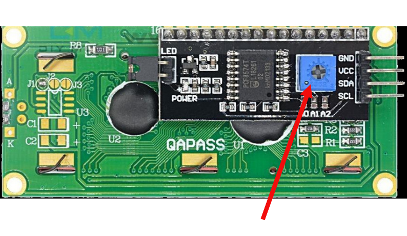
Turning this potentiometer slowly will make the characters clearer or darker until they are easy to read.
引脚布局
Pin Layout
When using the parallel interface, the LCD exposes a total of 16 pins. These pins provide power, contrast control, control signals, data lines, and backlight connections.
In the I2C interface, these signals are simplified and exposed through fewer pins. We will first look at the I2C variant, followed by the parallel interface.
I2C Pin Layout
The I2C adapter simplifies the connection by converting I2C commands into parallel signals internally. From the microcontroller side, we only need power and the two I2C lines.
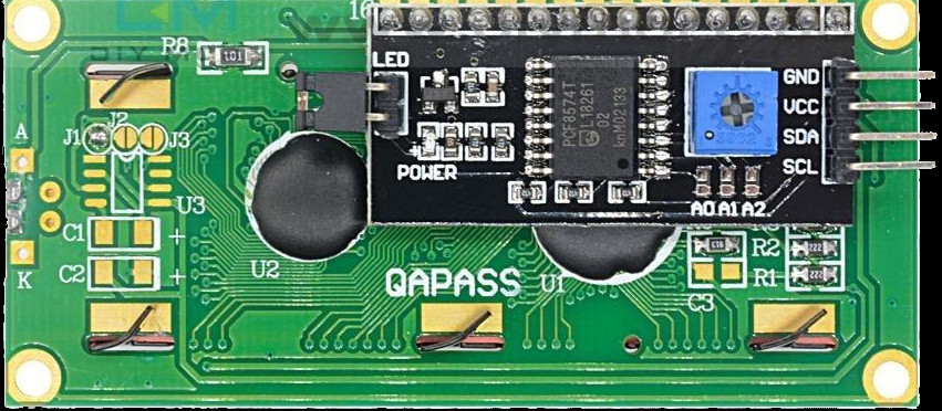
| Pin | Label | Description |
|---|---|---|
| 1 | VCC | Power supply (typically 5 V) |
| 2 | GND | Ground |
| 3 | SDA | Serial Data Line for I2C communication |
| 4 | SCL | Serial Clock Line for I2C communication |
Parallel Interface Pin Layout
In the parallel interface, the microcontroller talks directly to the HD44780 controller. This gives more control but requires more wiring and careful timing.
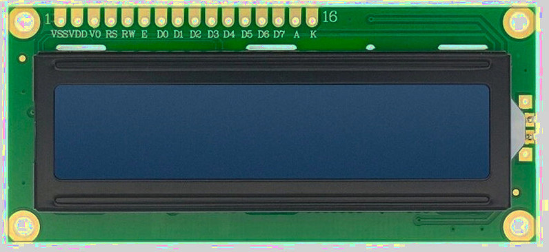
| Pin Position | LCD Pin | Details |
|---|---|---|
| 1 | VSS | Ground (GND). |
| 2 | VDD | Power supply for the LCD logic, typically 5 V. |
| 3 | Vo |
Contrast control pin. - This pin expects an analog voltage between GND and VDD. - Recommended: Use a 10 k potentiometer as a voltage divider, with the wiper connected to Vo and the other two pins to VDD and GND. - Alternative: Use fixed resistors as a voltage divider between VDD and GND, with the midpoint connected to Vo. |
| 4 | RS |
Register Select: - LOW (RS = 0): Instruction or command register. - HIGH (RS = 1): Data register. |
| 5 | RW |
Read or Write control: - LOW (RW = 0): Write to LCD. - HIGH (RW = 1): Read from LCD. - Commonly tied to GND for write-only operation. |
| 6 | E | Enable pin. Data or commands are latched on the HIGH to LOW transition of this pin. |
| 7–10 | D0–D3 | Lower data bits. Used only in 8-bit mode. Leave unconnected when using 4-bit mode. |
| 11–14 | D4–D7 | Higher data bits. Used for data transfer in both 4-bit and 8-bit modes. In 4-bit mode, all data is sent using only these pins. |
| 15 | A | Backlight anode. Often connected to 5 V. Some modules include an onboard current-limiting resistor. |
| 16 | K | Backlight cathode. Connect to GND. |
Contrast Adjustment
The Vo pin controls the contrast of the LCD by setting the voltage difference between VDD and Vo. Lower Vo values increase contrast, while higher values reduce it.
The recommended approach is to use a potentiometer connected between VDD and GND, with the wiper connected to Vo. This allows easy adjustment while the LCD is powered.
If a potentiometer is not available, fixed resistors can be used as a voltage divider between VDD and GND, with the midpoint connected to Vo.
Register Select Pin (RS)
The RS pin selects whether the LCD interprets incoming values as commands or as character data.
- RS = LOW: command mode
- RS = HIGH: data mode
Enable Pin (E)
The Enable pin controls when data is latched into the LCD.
To send data or a command, place the value on the data pins, set RS appropriately, then pulse E HIGH and bring it back LOW. The LCD reads the data on the HIGH to LOW transition.
It is used to control when data is transferred to the LCD display. The enable pin is typically kept low (E=0) but is set high (E=1) for a specific period of time to initiate a data transfer, and then returned to low.. The data is latched into the LCD on the transition from high to low.
Connecting LCD Display (LCD1602) to the Raspberry Pi Pico
We are going to connect an LCD1602 character display fitted with an I2C adapter to the Raspberry Pi Pico. From a wiring point of view, the setup looks simple because only four connections are required: power, ground, SDA, and SCL. However, even though the wiring count is small, there is an important voltage detail that we must handle correctly before making any connections.
Voltage compatibility problem
The Raspberry Pi Pico’s GPIO pins are 3.3 V tolerant. Anything significantly above 3.3 V on SDA or SCL can damage the Pico, either immediately or gradually over time.
Most LCD1602 modules with an I2C backpack are designed to run at 5 V. The I2C backpack usually has pull-up resistors connected to its supply voltage. When powered at 5 V, this means SDA and SCL idle at 5 V.
If SDA and SCL from such a module are connected directly to the Pico, the Pico GPIO pins will be exposed to 5 V. This is the core problem we must address.
A commonly suggested shortcut you will see online
Many online tutorials suggest powering the LCD1602 and its I2C backpack from 5 V and connecting SDA and SCL directly to the Pico. I have tested this setup myself, and it does work. However, it is electrically unsafe, and long-term use can damage the Pico GPIO pins.
For this reason, even though it functions, this wiring method should not be considered safe or recommended.
The lazy but reasonably safe approach: power everything at 3.3 V
For demos, experiments, and learning projects, the simplest and safest approach is to power the LCD1602 I2C module from the Pico 3.3 V rail instead of 5 V.
When the LCD backpack is powered at 3.3 V, its I2C pull-up resistors pull SDA and SCL to 3.3 V instead of 5 V. This immediately removes the voltage compatibility problem, and SDA and SCL can be connected directly to the Pico.
The trade-off is that the LCD contrast and backlight brightness will be reduced. In most indoor environments, the display remains readable and is usually more than adequate for demonstrations and testing.
This approach avoids extra components, and avoids stressing the Pico GPIO pins.
| LCD Pin | Wire | Pico Pin | Notes |
|---|---|---|---|
| GND |
|
GND | Common ground |
| VCC |
|
3.3 V | 3.3 power supply for the LCD |
| SCL |
|
GPIO 17 | I2C clock line (I2C0 SCL) |
| SDA |
|
GPIO 16 | I2C data line (I2C0 SDA) |
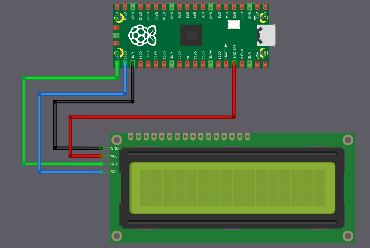
Best approach: Using a level shifter
If you need full backlight brightness, or if your LCD module does not work reliably at 3.3 V, then you must power it at 5 V. But this means you need to protect your Pico from the 5 V signals.
The solution is a bidirectional logic level converter (also called a level shifter). This small module converts signals between 3.3 volts and 5 volts in both directions. You can find these as “2-Channel” or “4-Channel I2C/SPI Logic Level Converter” modules.
The Pico connects to the 3.3 V side of the level shifter, the LCD connects to the 5 V side. The level shifter makes sure the Pico only ever sees 3.3 V signals, while the LCD gets the 5 V signals it needs.
This is the electrically correct and safe method, but it adds a few extra wires and requires an additional module.
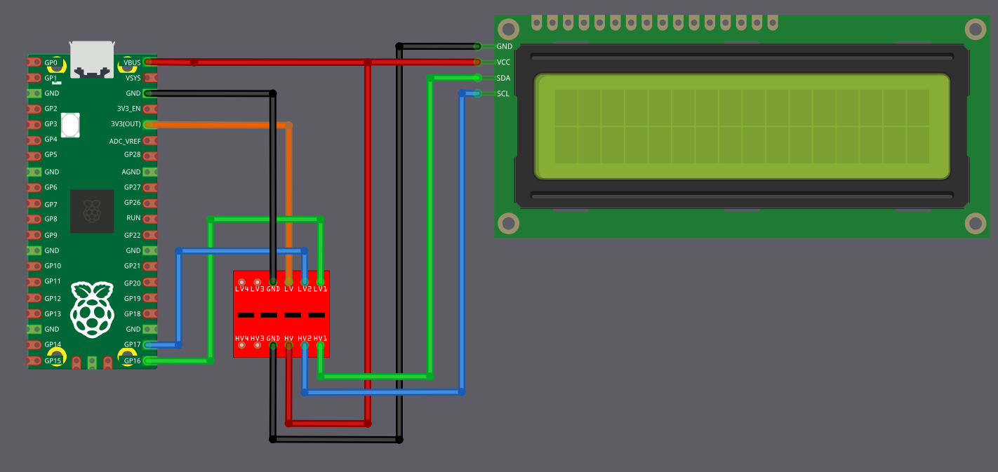
The circuit diagram may look a little confusing at first glance, but the idea is simple once you break it down.
Power Connections (Connect These First)
First, connect the Pico 3.3 V output to the pin marked LV (Low Voltage) on the level shifter. Connect the Pico VBUS (5 V) to the pin marked HV (High Voltage) on the level shifter. The LCD VCC pin is also powered directly from the Pico VBUS pin. Ground must be common, so connect Pico GND, the level shifter GND, and the LCD GND together.
| From | Pin | Wire | To | Pin | Purpose |
|---|---|---|---|---|---|
| Raspberry Pi Pico | GND |
|
Level Shifter | GND | Common ground |
| Level Shifter | GND |
|
LCD Display | GND | Common ground |
| Raspberry Pi Pico | 3.3 V |
|
Level Shifter | LV | Low voltage power (3.3 V side) |
| Raspberry Pi Pico | VBUS (5 V) |
|
Level Shifter | HV | High voltage power (5 V side) |
| Raspberry Pi Pico | VBUS (5 V) |
|
LCD Display | VCC | 5 V power supply for the LCD |
Data Connections (I2C Communication)
Now coming to the I2C lines. The Pico pins must always connect to the pins on the level shifter marked LVx, and the LCD pins must always connect to the corresponding pins marked HVx. Pico GPIO 16 (SDA) connects to LV1, and the LCD SDA pin connects to HV1. Pico GPIO 17 (SCL) connects to LV2, and the LCD SCL pin connects to HV2.
| From | Pin | Wire | To | Pin | Purpose |
|---|---|---|---|---|---|
| Raspberry Pi Pico | GPIO 16 |
|
Level Shifter | LV1 | SDA (Data) - Pico side |
| Level Shifter | HV1 |
|
LCD Display | SDA | SDA (Data) - LCD side |
| Raspberry Pi Pico | GPIO 17 |
|
Level Shifter | LV2 | SCL (Clock) - Pico side |
| Level Shifter | HV2 |
|
LCD Display | SCL | SCL (Clock) - LCD side |
How it works?
In simple terms, when the Pico communicates over an I2C line, the LVx side operates at 3.3 V, and the level shifter presents a 5 V signal on the matching HVx side for the LCD. When the LCD communicates at 5 V, the level shifter translates that signal back so the Pico only ever sees 3.3 V on the LVx side. This way, both devices operate at their required voltages without stressing the Pico GPIO pins.
C 实现
“Hello, Rust!” in LCD Display
We will create a simple program that prints “Hello, Rust!” on the LCD screen. This helps us quickly check that the wiring, I2C setup, and LCD configuration are correct before moving on to the next exercise.
HD44780 Drivers
You can find driver crates by searching for the hardware controller name HD44780. Sometimes searching by the display module name, such as lcd1602, also works.
While looking around, I came across several Rust crates that can control this LCD. Some of them even support async. You could also write your own driver by referring to the datasheet, but that is beyond the scope of this chapter.
Tip
If you want to learn how to write your own embedded Rust drivers, you can refer to the Rust Embedded Drivers (RED) book
For now, we will use one of the existing crates. You are free to try other crates later. Just read the crate documentation and adapt the code if needed.
In this exercise, we will use this crate: hd44780-driver
Project from template
We will start by creating a new project using the template.
cargo generate --git https://github.com/ImplFerris/pico2-template.git --tag v0.3.2
When prompted, give your project a name, like “hello-lcd” and select embassy as the HAL.
Additional Crates required
Add the following dependency to Cargo.toml along with the existing ones:
#![allow(unused)]
fn main() {
hd44780-driver = "0.4.0"
}Additional imports
Add the imports required for I2C and the LCD driver.
#![allow(unused)]
fn main() {
// I2C
use embassy_rp::i2c::Config as I2cConfig;
use embassy_rp::i2c::{self}; // for convenience, importing as alias
// LCD Driver
use hd44780_driver::HD44780;
use embassy_time::Delay;
}I2C Address
LCD1602 I2C adapters typically use address 0x27, though some modules use 0x3F instead depending on the adapter. Check your module’s datasheet or try both addresses if you’re unsure.
#![allow(unused)]
fn main() {
const LCD_I2C_ADDRESS: u8 = 0x27;
}I2C Setup
We’ll configure the I2C interface using GPIO 16 for SDA and GPIO 17 for SCL, with a frequency of 100 kHz.
#![allow(unused)]
fn main() {
let sda = p.PIN_16;
let scl = p.PIN_17;
let mut i2c_config = I2cConfig::default();
i2c_config.frequency = 100_000; //100kHz
let i2c = i2c::I2c::new_blocking(p.I2C0, scl, sda, i2c_config);
}LCD Initialization
Now let’s create the LCD driver instance with our I2C interface:
#![allow(unused)]
fn main() {
// LCD Init
let mut lcd =
HD44780::new_i2c(i2c, LCD_I2C_ADDRESS, &mut Delay).expect("failed to initialize lcd");
}Clear the Display
Before we write anything, we’ll reset and clear the screen:
#![allow(unused)]
fn main() {
// Clear the screen
lcd.reset(&mut Delay).expect("failed to reset lcd screen");
lcd.clear(&mut Delay).expect("failed to clear the screen");
}Write Text to the LCD
Finally, let’s write our message to the LCD:
#![allow(unused)]
fn main() {
// Write to the top line
lcd.write_str("Hello, Rust!", &mut Delay)
.expect("failed to write text to LCD");
}Clone the existing project
You can clone (or refer) project I created and navigate to the hello-lcd folder.
git clone https://github.com/ImplFerris/pico2-embassy-projects
cd pico2-embassy-projects/lcd/hello-lcd/
rp-hal version
You can clone (or refer) project I created and navigate to the hello-lcd folder.
git clone https://github.com/ImplFerris/pico2-rp-projects
cd pico2-rp-projects/lcd/hello-lcd/
Supported Characters
When referring to the HD44780 datasheet, you’ll find two character set tables corresponding to two different ROM versions(A00 and A02). To determine which ROM your display uses, try unique characters from both tables. The one that displays correctly indicates the ROM version. Once identified, you only need to refer to the relevant table.
In my case, the LCD module I’m using is based on ROM version A00. I’ll present the A00 table and explain how to interpret it, though the interpretation logic is the same for both versions.

It’s an 8-bit character, where the upper 4 bits come first, followed by the lower 4 bits, to form the complete character byte. In the reference table, the upper 4 bits correspond to the columns, while the lower 4 bits correspond to the rows.
For example, to get the binary representation of the character “#,” the upper 4 bits are 0010, and the lower 4 bits are 0011. Combining them gives the full binary value 00100011. In Rust, you can represent this value either in binary (0b00100011) or as a hexadecimal (0x23).
hd44780-driver crate
In the hd44780-driver crate we are using, we can write characters directly as a single byte or a sequence of bytes.
Write single byte
#![allow(unused)]
fn main() {
lcd.write_byte(0x23, &mut timer).unwrap();
lcd.write_byte(0b00100011, &mut timer).unwrap();
}Write multiple bytes
#![allow(unused)]
fn main() {
lcd.write_bytes(&[0x23, 0x24], &mut timer).unwrap();
}Custom Glyphs
Besides the supported characters, you can create your own custom characters (glyphs), like smileys or heart symbols. The module includes 64 bytes of Character Generator RAM (CGRAM), allowing up to 8 custom glyphs.
The controller provides 64 bytes of Character Generator RAM (CGRAM). Each custom glyph occupies 8 bytes, so you can store up to 8 custom glyphs at a time.
Each glyph is an 8x8 grid, where each row is represented by a single 8-bit value (u8). This makes it 8 bytes per glyph (8 rows × 1 byte per row). That is why, with a total of 64 bytes, you can only store up to 8 custom glyphs (8 glyphs × 8 bytes = 64 bytes).
Note
If you recall, in our LCD module, each character is represented as a 5 × 8 grid. But wait, didn’t we say we need an 8 × 8 grid for the characters? Yes, that’s correct-we need 8 × 8 (8 bytes) memory, but we only use 5 bits in each row. The 3 high-order bits in each row are left as zeros.
生成器
LCD Custom Character Generator (5x8 Grid)
Select the grids to create a symbol or character. As you select the grid, the corresponding bits in the byte array will be updated.
Generated Array
Ferris on LCD Display
In this section, we will draw Ferris on a character LCD. This is my attempt at making it look like a crab. If you come up with a better design, feel free to send a pull request.
Although a single custom character is limited to one 5x8 cell, we are not restricted to just one cell. By combining 4 or even 6 adjacent grids, we can display a larger symbol. How far you take this is entirely up to your creativity.
We will use the custom glyph generator from the previous page to design Ferris. The generator produces the byte array that we can directly use in our code.
liquid_crystal crate
The hd44780-driver crate that we used earlier does not support defining custom glyphs. To work with custom glyphs stored in CGRAM, we will use the liquid_crystal crate.
This crate supports custom glyphs and also provides an async API, which we will use in this chapter.
Update Cargo.toml
Enable the async feature when adding the dependency:
liquid_crystal = { version = "0.2.0", features = ["async"] }
Additional imports
Add these imports at the top of your main.rs:
#![allow(unused)]
fn main() {
// Interrupt Binding
use embassy_rp::peripherals::I2C0;
use embassy_rp::{bind_interrupts, i2c};
// I2C
use embassy_rp::i2c::{Config as I2cConfig, I2c};
// LCD Driver
use liquid_crystal::I2C;
use liquid_crystal::LiquidCrystal;
use liquid_crystal::prelude::*;
use embassy_time::Delay;
}Bind I2C Interrupt
Bind the I2C0_IRQ interrupt to the Embassy I2C interrupt handler for I2C0:
#![allow(unused)]
fn main() {
bind_interrupts!(struct Irqs {
I2C0_IRQ => i2c::InterruptHandler<I2C0>;
});
}Initialize I2C
First, set up the I2C bus to communicate with the display:
#![allow(unused)]
fn main() {
let sda = p.PIN_16;
let scl = p.PIN_17;
let mut i2c_config = I2cConfig::default();
i2c_config.frequency = 100_000; // 100kHz
let i2c_bus = I2c::new_async(p.I2C0, scl, sda, Irqs, i2c_config);
}Initialize the LCD interface
Once the I2C interface is set up, we initialize the LCD.
#![allow(unused)]
fn main() {
// LCD Init
let mut i2c_interface = I2C::new(i2c_bus, 0x27);
let mut lcd = LiquidCrystal::new(&mut i2c_interface, Bus4Bits, LCD16X2);
lcd.begin(&mut Delay);
}Generated byte array for the custom glyph
#![allow(unused)]
fn main() {
const FERRIS: [u8; 8] = [
0b01010, 0b10001, 0b10001, 0b01110, 0b01110, 0b01110, 0b11111, 0b10001,
];
// Define the character
lcd.custom_char(&mut Delay, &FERRIS, 0);
}Displaying
Displaying the character is straightforward. You just need to use the CustomChar enum and pass the index of the custom character. We’ve defined only one custom character, which is at position 0.
#![allow(unused)]
fn main() {
lcd.write(&mut Delay, CustomChar(0));
lcd.write(&mut Delay, Text(" implRust!"));
}Clone the existing project
You can clone (or refer) project I created and navigate to the custom-glyph folder.
git clone https://github.com/ImplFerris/pico2-embassy-projects
cd pico2-embassy-projects/lcd/custom-glyph/
rp-hal version
You can clone (or refer) project I created and navigate to the custom-glyph folder.
git clone https://github.com/ImplFerris/pico2-rp-projects
cd pico2-projects/lcd/custom-glyph/
The Full code
#![no_std]
#![no_main]
use embassy_executor::Spawner;
use embassy_rp as hal;
use embassy_rp::block::ImageDef;
use embassy_time::Timer;
//Panic Handler
use panic_probe as _;
// Defmt Logging
use defmt_rtt as _;
// Interrupt Binding
use embassy_rp::peripherals::I2C0;
use embassy_rp::{bind_interrupts, i2c};
// I2C
use embassy_rp::i2c::{Config as I2cConfig, I2c};
// LCD Driver
use liquid_crystal::I2C;
use liquid_crystal::LiquidCrystal;
use liquid_crystal::prelude::*;
use embassy_time::Delay;
/// Tell the Boot ROM about our application
#[unsafe(link_section = ".start_block")]
#[used]
pub static IMAGE_DEF: ImageDef = hal::block::ImageDef::secure_exe();
bind_interrupts!(struct Irqs {
I2C0_IRQ => i2c::InterruptHandler<I2C0>;
});
// const LCD_I2C_ADDRESS: u8 = 0x27;
#[embassy_executor::main]
async fn main(_spawner: Spawner) {
let p = embassy_rp::init(Default::default());
let sda = p.PIN_16;
let scl = p.PIN_17;
let mut i2c_config = I2cConfig::default();
i2c_config.frequency = 100_000; //100kHz
let i2c_bus = I2c::new_async(p.I2C0, scl, sda, Irqs, i2c_config);
// LCD Init
let mut i2c_interface = I2C::new(i2c_bus, 0x27);
let mut lcd = LiquidCrystal::new(&mut i2c_interface, Bus4Bits, LCD16X2);
lcd.begin(&mut Delay);
const FERRIS: [u8; 8] = [
0b01010, 0b10001, 0b10001, 0b01110, 0b01110, 0b01110, 0b11111, 0b10001,
];
// Define the character
lcd.custom_char(&mut Delay, &FERRIS, 0);
lcd.write(&mut Delay, CustomChar(0));
// normal text
lcd.write(&mut Delay, Text(" implRust!"));
loop {
Timer::after_millis(100).await;
}
}
// Program metadata for `picotool info`.
// This isn't needed, but it's recomended to have these minimal entries.
#[unsafe(link_section = ".bi_entries")]
#[used]
pub static PICOTOOL_ENTRIES: [embassy_rp::binary_info::EntryAddr; 4] = [
embassy_rp::binary_info::rp_program_name!(c"custom-chars"),
embassy_rp::binary_info::rp_program_description!(c"your program description"),
embassy_rp::binary_info::rp_cargo_version!(),
embassy_rp::binary_info::rp_program_build_attribute!(),
];
// End of file多字符生成器
Multi-Cell Custom Glyph Generator
This is used when you want to combine multiple grids to create a symbol. You can utilize adjacent grids on the 16 × 2 LCD display to design a custom symbol or character. You can view the example symbol created with this generator and how to use in Rust in the next page.
Generated Array
Multi-Cell Custom Glyph
In this section, we create Ferris using six adjacent grids with the generator from the previous page. Below is the Rust code that uses the generated byte arrays to render the glyph on the LCD.

We will focus only on the glyph composition here. Project setup and LCD initialization remain the same as before and are not repeated in this section.
Generated Byte array for the characters
#![allow(unused)]
fn main() {
const SYMBOL1: [u8; 8] = [
0b00110, 0b01000, 0b01110, 0b01000, 0b00100, 0b00011, 0b00100, 0b01000,
];
const SYMBOL2: [u8; 8] = [
0b00000, 0b00000, 0b00000, 0b10001, 0b10001, 0b11111, 0b00000, 0b00000,
];
const SYMBOL3: [u8; 8] = [
0b01100, 0b00010, 0b01110, 0b00010, 0b00100, 0b11000, 0b00100, 0b00010,
];
const SYMBOL4: [u8; 8] = [
0b01000, 0b01000, 0b00100, 0b00011, 0b00001, 0b00010, 0b00101, 0b01000,
];
const SYMBOL5: [u8; 8] = [
0b00000, 0b00000, 0b00000, 0b11111, 0b01010, 0b10001, 0b00000, 0b00000,
];
const SYMBOL6: [u8; 8] = [
0b00010, 0b00010, 0b00100, 0b11000, 0b10000, 0b01000, 0b10100, 0b00010,
];
}Declare them as character
Each glyph is stored in a separate CGRAM slot. We use slots 0 through 5 for this example.
#![allow(unused)]
fn main() {
lcd.custom_char(&mut Delay, &SYMBOL1, 0);
lcd.custom_char(&mut Delay, &SYMBOL2, 1);
lcd.custom_char(&mut Delay, &SYMBOL3, 2);
lcd.custom_char(&mut Delay, &SYMBOL4, 3);
lcd.custom_char(&mut Delay, &SYMBOL5, 4);
lcd.custom_char(&mut Delay, &SYMBOL6, 5);
}Display
We write the first three glyphs on the first row, followed by the remaining three glyphs on the second row, aligning them to form a single composite symbol.
#![allow(unused)]
fn main() {
lcd.set_cursor(&mut Delay, 0, 4)
.write(&mut Delay, CustomChar(0))
.write(&mut Delay, CustomChar(1))
.write(&mut Delay, CustomChar(2));
lcd.set_cursor(&mut Delay, 1, 4)
.write(&mut Delay, CustomChar(3))
.write(&mut Delay, CustomChar(4))
.write(&mut Delay, CustomChar(5));
}Clone the existing project
You can clone (or refer) project I created and navigate to the mutli-glyph folder.
git clone https://github.com/ImplFerris/pico2-embassy-projects
cd pico2-embassy-projects/lcd/mutli-glyph/
rp-hal version
A version using rp-hal is also available:
git clone https://github.com/ImplFerris/pico2-rp-projects
cd pico2-projects/lcd/mutli-glyph/
Symbols Index
Here is a list of custom symbols with their corresponding byte arrays. If you’ve designed an interesting symbol and want to add to this list, feel free to submit a pull request. Please use the custom character generator provided here to ensure consistency.
| Title | Preview | Byte Array |
|---|---|---|
| Heart |  |
[ 0b00000, 0b01010, 0b11111, 0b11111, 0b01110, 0b00100, 0b00000, 0b00000,] |
| Lock |  |
[ 0b01110, 0b10001, 0b10001, 0b11111, 0b11011, 0b11011, 0b11011, 0b11111, ] |
| Hollow Heart |  |
[ 0b00000, 0b01010, 0b10101, 0b10001, 0b10001, 0b01010, 0b00100, 0b00000, ] |
| Battery |  |
[ 0b01110, 0b11011, 0b10001, 0b10001, 0b10001, 0b11111, 0b11111, 0b11111, ] |
| Bus |  |
[ 0b01110, 0b11111, 0b10001, 0b10001, 0b11111, 0b10101, 0b11111, 0b01010, ] |
| Bell |  |
[ 0b00100, 0b01110, 0b01110, 0b01110, 0b11111, 0b00000, 0b00100, 0b00000, ] |
| Hour Glass |  |
[ 0b00000, 0b11111, 0b10001, 0b01010, 0b00100, 0b01010, 0b10101, 0b11111, ] |
| Charger |  |
[ 0b01010, 0b01010, 0b11111, 0b10001, 0b10001, 0b01110, 0b00100, 0b00100, ] |
| Tick Mark |  |
[ 0b00000, 0b00000, 0b00001, 0b00011, 0b10110, 0b11100, 0b01000, 0b00000, ] |
| Music Note |  |
[ 0b00011, 0b00010, 0b00010, 0b00010, 0b00010, 0b01110, 0b11110, 0b01110, ] |
ADC (Analog to Digital Converter)
I hope you are already familiar with the idea of analog and digital signals. The world around us is mostly analog. Temperature rises and falls smoothly, light intensity changes gradually, sound moves through the air as waves, and sensors produce voltages that change continuously.
Microcontrollers, however, only understand discrete values. Internally, everything is represented as binary numbers, ones and zeros, HIGH and LOW. This creates a basic gap between the real world and digital logic. How does a digital system understand something that changes smoothly?
This is where the Analog to Digital Converter (ADC) comes in. An ADC measures an analog voltage and converts it into a digital number that our microcontrollers can process, store, and act upon.
You may recall from the earlier chapter on PWM that we explored how a digital system can create an analog-like output by rapidly switching a pin on and off. ADC does the opposite. It allows the microcontroller to read and understand analog inputs from the real world. Together, peripherals like PWM and ADC allow embedded systems to both sense their environment and control it.
Consider a simple example: a temperature monitoring system. A temperature sensor outputs a voltage that changes with temperature, for example 0 V at 0 °C and 3.3 V at 100 °C. Without an ADC, this smooth voltage signal would be meaningless to the microcontroller. The ADC samples the voltage at regular intervals and converts each sample into a digital value. Your code can then read that value, interpret it as a temperature, and respond accordingly.
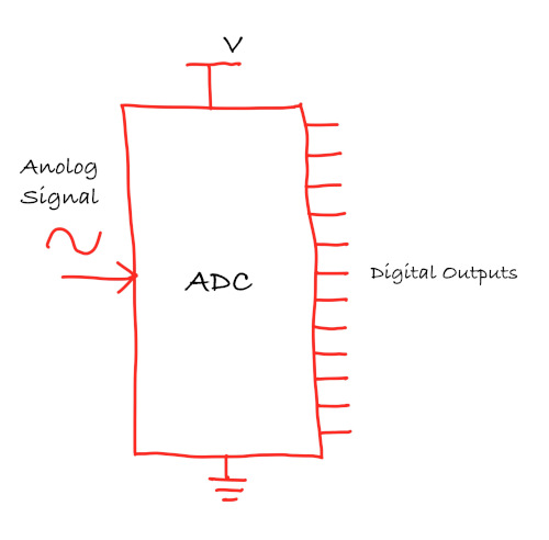
ADC Resolution
One of the most important characteristics of an ADC is its resolution, which determines how finely it can divide the analog input range into discrete digital values. Resolution is typically expressed in bits, such as 8-bit, 10-bit, or 12-bit. The number of bits decides how many different values the ADC can produce.
An 8-bit ADC divides its input voltage range into 256 distinct levels (28). A 10-bit ADC provides 1,024 levels (210), and a 12-bit ADC offers 4,096 levels(212). As you can see, each additional bit doubles the number of levels, significantly improving precision. The more bits your ADC has, the smaller the voltage differences it can distinguish.
Example
Let’s make this concrete with an example. Suppose you are using a 10-bit ADC with a reference voltage of 3.3 V. The ADC will represent voltages from 0 V to 3.3 V as digital values from 0 to 1,023.
The smallest voltage change the ADC can detect (called the step size) is calculated as:
\[ \text{Step Size} = \frac{\text{Vref}}{2^{\text{bits}}} \]
Step Size = 3.3 V / 1,024 = 3.22 mV
This means the ADC cannot tell the difference between two voltages that are closer than about 3.22 mV. For example, if a sensor output changes from 1.500 V to 1.502 V, the ADC will likely report the same digital value for both.
Compare this to a 12-bit ADC with the same 3.3 V reference:
Step Size = 3.3 V / 4,096 = 0.81 mV
The 12-bit converter offers significantly finer precision, which can be critical in applications requiring accurate measurements.
ADC Formula
Conceptually, an ADC converts an input voltage into a digital number using the following relationship:
\[ ADC = \frac{V_{in}}{V_{ref}} \times 2^{\text{bits}} \]
Where:
- \(V_{in}\) is the input voltage
- \(V_{ref}\) is the reference voltage
Converting ADC Values to Voltage
When you read from the ADC in your code, it returns a raw digital value between 0 and 4095 (for a 12-bit ADC). This number represents where the measured voltage falls within the 0 V to 3.3 V range. To convert this raw value back into an actual voltage, you need a simple calculation.
The conversion formula is:
\[ \text{Voltage} = \frac{\text{ADC Reading} \times \text{Reference Voltage}}{2^{\text{bits}}} \]
For the RP2350 with its 12-bit ADC and 3.3 V reference voltage:
\[ \text{Voltage} = \frac{\text{ADC Reading} \times 3.3}{4096} \]
Example
Let’s say we get an ADC reading of 1000.
Voltage = (1000 × 3.3) / 4096 = 0.806 V
Reference
In RP2350
The RP2350 microcontroller features a built-in 12-bit ADC with multiple input channels, giving you 4,096 distinct levels to represent voltages from 0 V to 3.3 V. With the 3.3 V reference voltage (ADC_AVDD), this produces a step size of approximately 0.806 mV. You can refer to page 1066 of the datasheet for more details: RP2350 datasheet
On the RP2350 chip, the ADC uses a pin called ADC_AVDD. This pin powers the ADC and also acts as the reference voltage for conversions. The value on this pin sets the maximum voltage the ADC can measure. In practice, ADC_AVDD is usually connected to 3.3 V. Because the ADC is sensitive to small voltage changes, this supply should be clean and stable to get reliable readings.
On the Raspberry Pi Pico 2 board, this is already taken care of for you. The board connects the 3.3 V supply to the RP2350 ADC_AVDD pin through a small filter made from a resistor and a capacitor. This helps reduce noise and improves ADC behavior.
The Pico 2 also exposes this filtered reference on a pin labeled ADC_VREF (physical pin 35). By default, you do not need to touch this pin. You can simply use the ADC as is. For more advanced use cases, this pin allows you to supply an external precision reference voltage if you need higher accuracy, but this is optional and not required for beginner projects
For now, it is enough to remember that the RP2350 ADC is 12-bit, measures voltages up to its reference voltage, and that the Pico 2 board already provides a safe and stable default setup.
ADC Channels and GPIO Mapping on Raspberry Pi Pico 2
The RP2350 ADC has multiple internal channels. On the Raspberry Pi Pico 2, four of these channels are connected to GPIO pins that can be used as analog inputs.
| GPIO Pin | ADC Channel | Function |
|---|---|---|
| GPIO26 | ADC0 | Can be used to read voltage from peripherals. |
| GPIO27 | ADC1 | Can be used to read voltage from peripherals. |
| GPIO28 | ADC2 | Can be used to read voltage from peripherals. |
| GPIO29 | ADC3 | Measures the VSYS supply voltage on the board. |
Voltage Divider with ADC
Sometimes you need to measure voltages higher than the ADC’s reference voltage (3.3 V). For example, measuring a 5 V power supply, a 9 V battery, or a 12 V system. Since the RP2350 ADC can only safely measure up to 3.3 V, you need to scale down the voltage using a voltage divider.
We have already seen how the voltage divider works and how two resistors can be used to scale a voltage. If you need a refresher on how voltage dividers work, refer back to the voltage divider section. Here, we will focus on how a voltage divider interacts with an ADC and how the divider output turns into an ADC reading.
Tip
Voltage dividers are not just for scaling voltages. Sensors like LDRs and thermistors are resistors whose values change with light or temperature. When used in a voltage divider, these resistance changes turn into voltage changes that the ADC can read.
Using Voltage Dividers with ADC
When using a voltage divider with an ADC, the goal is usually to scale a voltage so that it stays within the ADC input range. Design the voltage divider so that the maximum expected input voltage produces an output voltage below the ADC reference voltage.
For a 3.3 V system, it is good practice to aim for 3.0 V or less to allow some margin for supply variation and noise.
Example: Measuring a 3.3 V Supply
Consider a simple example where the input voltage is 3.3 V and we use resistor values of R1 = 10 kΩ and R2 = 1 kΩ.
You should already be familiar with the voltage divider formula:
\[ V_{out} = V_{in} \times \frac{R_2}{R_1 + R_2} \]
Using the voltage divider equation:
\[ V_{out} = 3.3 V \times \frac{1k}{1k + 10k} = 3.3 V \times \frac{1k}{11k} = 0.3 V \]
This output voltage is well within the ADC input range. The divider output voltage V_out is connected to an ADC input pin.
C 实现
Light Dependent Resistors (LDRs)
Light Dependent Resistors (LDRs), also known as photoresistors, are among the simplest sensors you can use with a microcontroller. Their resistance changes based on the amount of light falling on them. More light results in lower resistance, while less light results in higher resistance.
Because of this behavior, LDRs are commonly used in projects such as automatic street lights, screen brightness control, light meters, and basic day night detection.

How an LDR Works
An LDR is made from a photosensitive semiconductor material. When light hits its surface, photons transfer energy to the material and free up charge carriers. As a result, the resistance of the LDR decreases.
Tip
Think of the LDR as Dracula. In sunlight, he gets weaker, just like the resistance gets lower. In darkness, he gets stronger, just like the resistance gets higher.
The resistance change is not linear, and the exact values vary between different LDRs. For most embedded applications, this is not a problem. We usually care about relative light levels rather than precise measurements.
We will not go into the details of the semiconductor materials used in LDRs or the physics behind them. If you are curious and want to explore this further, you can read this article and do additional research: https://www.elprocus.com/ldr-light-dependent-resistor-circuit-and-working/
Components Needed:

You will need the following components:
- LDR (Light Dependent Resistor)
- Resistor (typically 10 kΩ); needed to create voltage divider
- Jumper wires (as usual)
Prerequisite
Before working with an LDR, you should already understand what a voltage divider is and how it works, as well as what an ADC is and how it converts an analog voltage into a digital value.
If you need a quick refresher, you can refer to these sections:
Simulation of LDR in Voltage Divider
To understand how an LDR behaves in a voltage divider, I created a simple simulation using Falstad. In the circuit, the LDR is shown as a resistor symbol with arrows pointing toward it, indicating incident light.
You can import the circuit file I created, voltage-divider-ldr.circuitjs.txt, import into the Falstad site and play around. I have also embedded a small simulator at the bottom of this page, so you can use either option.
In this configuration, the LDR is placed on the top of the voltage divider (i.e as R1), with a fixed resistor (as R2) at the bottom. This arrangement is commonly used because increasing light results in an increasing output voltage, which is intuitive when reading the value using an ADC.
Once the circuit is loaded, adjust the brightness slider and observe how the resistance of the LDR changes. At the same time, you can see how the output voltage \( V_{out} \) responds to those changes.
Important
Swapping the LDR and the fixed resistor will invert the behavior of the output voltage. If you place the LDR as R2 (the bottom resistor) in the voltage divider, the relationship between light level and \( V_{out} \) is inverted because the equation changes.
Example output for full brightness
When the LDR is exposed to strong light, its resistance is low. This causes a larger portion of the supply voltage to appear at the output, resulting in a higher voltage.
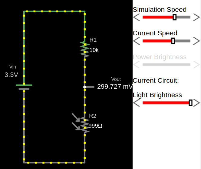
Example output for low light
As the light level decreases, the resistance of the LDR increases. This reduces the output voltage.
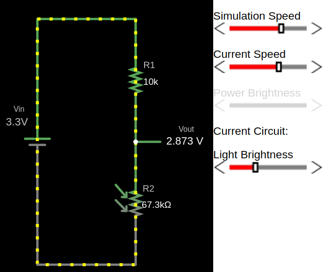
Example output for full darkness
In darkness, the LDR resistance becomes very high, causing the output voltage to drop near to zero.
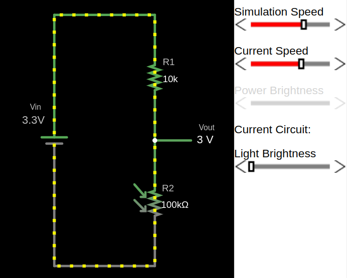
LDR Voltage Divider Simulator
C 实现
Turn on LED in low Light with Raspberry Pi Pico
In this exercise, we will build a small but practical project using an LDR. The Pico will automatically turn on an LED when the ambient light level drops below a certain point, meaning the LED turns on as it gets darker. You can extend this idea to control a real lamp, but that is outside the scope of this exercise and requires proper safety precautions.
You can try this in a closed room by switching the room light on and off. When the light is turned off and the room becomes dark enough, the LED should turn on, and it should turn off again when the room light is switched back on. Alternatively, you can adjust the sensitivity threshold or cover the LDR with your hand or another object to simulate different light levels.
Tip
You may need to adjust the ADC threshold based on your room’s lighting conditions and the specific LDR you are using.
Hardware Requirements
You are going to need the following components for this exercise:
- LED
- LDR
- Resistors
- 330 Ω: This is used with the LED to limit the current and protect it. You may need to choose a different value depending on the LED you are using.
- 10 kΩ: This is used with the LDR to form the voltage divider. You may need to adjust this value depending on the characteristics of your LDR.
- Jumper wires: These are used to connect everything together on a breadboard or directly to the microcontroller.
Circuit to Connect LED and LDR with Pico
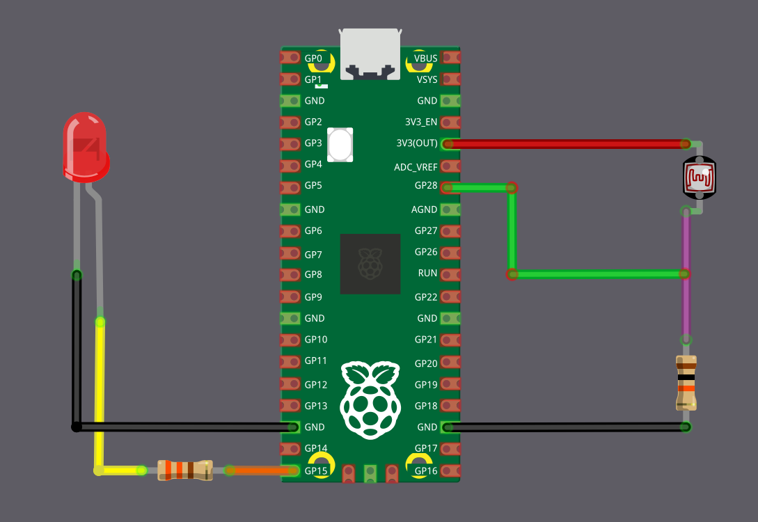
LDR (ADC) Connection
We are going to connect the LDR as a voltage divider and feed the divider output into an ADC pin on the Pico. Here, the LDR acts as R1 and is connected to the 3.3 V supply, which means the ADC value decreases as the light level drops.
| Pico Pin | Wire | Component |
|---|---|---|
| 3.3 V |
|
One end of the LDR |
| GPIO 28 (ADC2) |
|
Junction between LDR and 10 kΩ resistor |
| 10 kΩ resistor |
|
Other end of the LDR |
| GND |
|
Other end of the 10 kΩ resistor |
LED Connection
The LED will be connected to a GPIO pin 15 and will turn on automatically when the light level drops.
| Pico Pin | Wire | Component |
|---|---|---|
| GPIO 15 |
|
330 Ω resistor |
| 330 Ω resistor |
|
Anode (long leg) of LED |
| GND |
|
Cathode (short leg) of LED |
C 实现
Embedded Rust Code to Control an LED Based on Light Level
With the circuit assembled on your breadboard, let’s write the code.
Project from template
As usual, we are going to start by generating a new project from the template.
cargo generate --git https://github.com/ImplFerris/pico2-template.git --tag v0.3.2
When prompted, give your project a name, like “ldr-dracula” and select embassy as the HAL.
Additional Imports
#![allow(unused)]
fn main() {
// For Interrupt Binding
use embassy_rp::adc::InterruptHandler;
use embassy_rp::bind_interrupts;
// For ADC
use embassy_rp::adc::{Adc, Channel, Config as AdcConfig};
// For LED
use embassy_rp::gpio::{Level, Output, Pull};
}Interrupt Handler for ADC
The RP2350’s ADC has a FIFO (First-In-First-Out) buffer that stores conversion results (i.e, the measured voltage converted into a discrete ADC value). When this FIFO receives data, the hardware generates an interrupt signal called ADC_IRQ_FIFO.
In the Embassy library, the ADC interrupt handling logic is already implemented. We just need to bind this hardware interrupt so the ADC driver can use it.
Before we start reading values from the ADC, we need to set up this interrupt binding.
#![allow(unused)]
fn main() {
bind_interrupts!(struct Irqs {
ADC_IRQ_FIFO => InterruptHandler;
});
}ADC Threshold
Before we write the main logic, we need to decide what counts as low light. We do this by defining a threshold value for the ADC reading.
#![allow(unused)]
fn main() {
const LDR_THRESHOLD: u16 = 200;
}This threshold represents the light level at which the LED should turn on. When the ADC reading drops below this value, we treat the environment as dark. When the reading is above this value, we treat it as bright.
You may need to adjust this threshold depending on your room lighting, the LDR you are using, and the resistor values in the voltage divider.
Creating the ADC Instance
Let’s create the ADC instance.
#![allow(unused)]
fn main() {
let mut adc = Adc::new(p.ADC, Irqs, AdcConfig::default());
}Here, we pass three things to the ADC constructor. We pass the ADC peripheral itself, the interrupt bindings we defined earlier, and a default configuration.
Note
Interesting fact: the HAL does not actually do anything with
Irqsat runtime when you pass it to the ADC constructor. It is only there at compile time to make sure you have declared the ADC interrupt binding. If you follow the new method, you will notice the parameter is named_irq, which makes it clear that it is not used.
Configuring the ADC Pin
Next, we select which GPIO pin will be used as the ADC input.
#![allow(unused)]
fn main() {
let mut adc_pin = Channel::new_pin(p.PIN_28, Pull::None);
}Configuring the LED Output
Now we configure the GPIO pin that drives the LED.
#![allow(unused)]
fn main() {
let mut led = Output::new(p.PIN_15, Level::Low);
}Main loop
The logic is straightforward: read the ADC value, and if it’s lesser than threshold we defined earlier, we turn on the LED; otherwise, turn it off.
#![allow(unused)]
fn main() {
loop {
let adc_reading = adc
.read(&mut adc_pin)
.await
.expect("Unable to read the adc value");
defmt::info!("ADC value: {}", adc_reading);
if adc_reading < LDR_THRESHOLD {
led.set_high();
} else {
led.set_low();
}
Timer::after_secs(1).await;
}
}The full code
#![no_std]
#![no_main]
use embassy_executor::Spawner;
use embassy_rp as hal;
use embassy_rp::block::ImageDef;
use embassy_time::Timer;
// Interrupt Binding
use embassy_rp::adc::InterruptHandler;
use embassy_rp::bind_interrupts;
// ADC
use embassy_rp::adc::{Adc, Channel, Config as AdcConfig};
// For LED
use embassy_rp::gpio::{Level, Output, Pull};
//Panic Handler
use panic_probe as _;
// Defmt Logging
use defmt_rtt as _;
/// Tell the Boot ROM about our application
#[unsafe(link_section = ".start_block")]
#[used]
pub static IMAGE_DEF: ImageDef = hal::block::ImageDef::secure_exe();
bind_interrupts!(struct Irqs {
ADC_IRQ_FIFO => InterruptHandler;
});
const LDR_THRESHOLD: u16 = 200;
#[embassy_executor::main]
async fn main(_spawner: Spawner) {
let p = embassy_rp::init(Default::default());
let mut adc = Adc::new(p.ADC, Irqs, AdcConfig::default());
let mut adc_pin = Channel::new_pin(p.PIN_28, Pull::None);
let mut led = Output::new(p.PIN_15, Level::Low);
loop {
let adc_reading = adc
.read(&mut adc_pin)
.await
.expect("Unable to read the adc value");
defmt::info!("ADC value: {}", adc_reading);
if adc_reading < LDR_THRESHOLD {
led.set_high();
} else {
led.set_low();
}
Timer::after_secs(1).await;
}
}
// Program metadata for `picotool info`.
// This isn't needed, but it's recomended to have these minimal entries.
#[unsafe(link_section = ".bi_entries")]
#[used]
pub static PICOTOOL_ENTRIES: [embassy_rp::binary_info::EntryAddr; 4] = [
embassy_rp::binary_info::rp_program_name!(c"ldr-dracula"),
embassy_rp::binary_info::rp_program_description!(c"your program description"),
embassy_rp::binary_info::rp_cargo_version!(),
embassy_rp::binary_info::rp_program_build_attribute!(),
];
// End of fileClone the existing project
You can clone (or refer) project I created and navigate to the ldr-dracula folder.
git clone https://github.com/ImplFerris/pico2-embassy-projects
cd pico2-embassy-projects/ldr-dracula/
Thermistor
A thermistor is a resistor whose value changes with temperature. As temperature goes up or down, the resistance changes in a predictable way. The name “thermistor” is derived from a combination of the words “thermal” and “resistor.”
From the microcontroller point of view, a thermistor is just another resistor connected to an ADC pin. The ADC does not know anything about temperature. It only measures voltage. We do the rest in the code.
NTC vs PTC
There are two common types of thermistors.
An NTC thermistor has lower resistance at higher temperatures. This is the most common type used for temperature measurement in embedded systems.

A PTC thermistor has higher resistance at higher temperatures. These are usually used for protection or current limiting rather than precise sensing.
In this chapter, we are going to work with an NTC thermistor.
Reference
NTC and Voltage Divider
To understand how an NTC thermistor behaves in a voltage divider, I created a simple simulation using Falstad. In the circuit, the thermistor is shown as a resistor whose value changes with temperature.
You can import the circuit file I created, voltage-divider-thermistor.circuitjs.txt, into the Falstad website and experiment with it yourself. I have also embedded a small simulator at the bottom of this page, so you can use either option.
In this configuration, the NTC thermistor is placed on the top of the voltage divider (R1), with a fixed resistor at the bottom (R2). As the temperature changes, the resistance of the thermistor changes, and that directly affects the output voltage of the voltage divider.
Important
Swapping the thermistor and the fixed resistor will invert the behavior of the output voltage. If you place the thermistor as R2 instead of R1, increase in temperature will cause \( V_{out} \) to decrease instead.
Thermistor at 25 °C
The thermistor has a resistance of 10 kΩ at 25 °C, resulting in an output voltage (\( V_{out} \)) of 1.65 V.
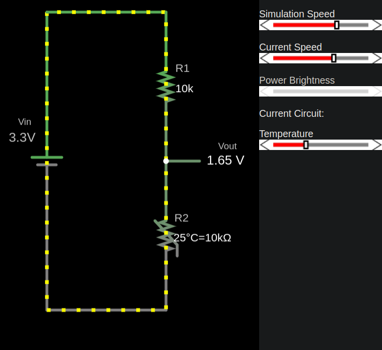
Thermistor at 10 °C
The thermistor’s resistance increases, resulting in a lower output voltage (\( V_{out} \)).
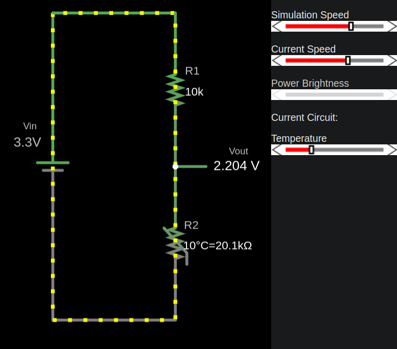
Thermistor at 100 °C
The thermistor’s resistance decreases due to its negative temperature coefficient. This results in increase of output voltage.
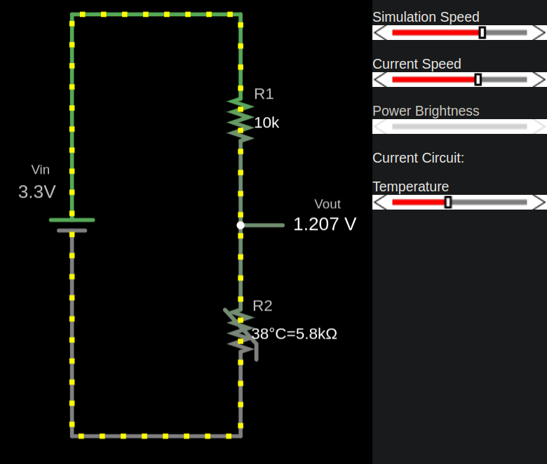
NTC Thermistor Voltage Divider Simulator
ADC to Resistance
When we connect a thermistor to the Pico, we do not read the voltage directly. What we get from the ADC is just a digital value that represents that voltage (refer to the ADC chapter).
But to calculate temperature, we actually need the resistance of the thermistor at that moment, not the ADC value itself.
In the next chapter, we are going to look at the temperature equations. Before we can use those formulas, we first need to convert the ADC reading back into the thermistor resistance. That is exactly what this chapter focuses on.
Converting ADC Reading to Thermistor Resistance
We now derive the thermistor resistance directly from the ADC reading using the voltage divider equation and the ADC conversion equation.
Step 1: Voltage at the divider midpoint
This is the standard voltage divider formula we have already seen. Since the thermistor is connected as R1, we label it explicitly as the thermistor resistance.
\[ V_{in} = \frac{R_2}{R_{thermistor} + R_2} \times V_{ref} \]
Step 2: ADC conversion equation
The ADC converts the input voltage into a digital value based on the ratio of the input voltage to the reference voltage.
\[ ADC = \frac{V_{in}}{V_{ref}} \times 2^{bits} \]
Step 3: Substitute the divider equation into the ADC equation
Substituting the expression for \( V_{in} \) into the ADC equation:
\[ ADC = \frac{\frac{R_2}{R_{thermistor} + R_2} \times V_{ref}}{V_{ref}} \times 2^{bits} \]
The \( V_{ref} \) terms cancel out, leaving:
\[ ADC = \frac{R_2}{R_{thermistor} + R_2} \times 2^{bits} \]
Step 4: Solve for thermistor resistance
Rearranging and solving for \( R_{thermistor} \):
\[ R_{thermistor} = \left( \frac{2^{bits}}{ADC} - 1 \right) \times R_2 \]
For the Pico, since it uses a 12-bit ADC, the equation can be simplified to:
\[ R_{thermistor} = \left( \frac{4096}{ADC} - 1 \right) \times R_2 \]
At this point, the equation contains only the ADC result, which is measured, and \( R_2 \), which is a known resistor value. Because \( R_2 \) directly affects the calculated thermistor resistance, it should be a temperature-stable resistor. Any variation in \( R_2 \) with temperature will directly affect the accuracy of the measurement.
In the next chapter, we will use this resistance value to calculate the temperature.
Rust Function
A simple helper function that converts an ADC reading into the corresponding thermistor resistance.
const ADC_LEVELS: f64 = 4096.0;
const R2_RES: f64 = 10_000.0; // R2
fn adc_to_resistance(adc_value: u16, r2_res:f64) -> f64 {
let adc = adc_value as f64;
((ADC_LEVELS / adc) - 1.0) * r2_res
}
fn main() {
let adc_value = 2000; // Our example ADC value;
let r2 = adc_to_resistance(adc_value, R2_RES);
println!("Calculated Resistance (R2): {} Ω", r2);
}Thermistor Non-Linearity
We learned how to use a thermistor in a voltage divider and how to calculate the thermistor resistance at a given moment. The next step is to determine the temperature corresponding to that resistance.
This step is not simple. Thermistors are non-linear devices, which means resistance does not change in a straight line with temperature. Because of this, resistance cannot be converted to temperature using a single linear formula.
The non-linear curve problem
A thermistor does not change resistance evenly as temperature changes. The relationship between temperature and resistance follows a curve.
At lower temperatures, a small change in temperature produces a large change in resistance. At higher temperatures, the same temperature change produces a much smaller resistance change. This behavior is a fundamental property of thermistors.
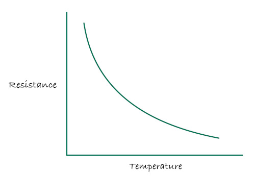
Because of this curve, there is no simple rule such as:
a fixed number of ohms equals one degree
Using known reference points
Thermistor manufacturers are aware of this behavior and provide detailed datasheets. These datasheets list resistance values at specific temperatures.
Each entry in the datasheet represents a known and measured point on the thermistor curve. Together, these points describe how resistance changes across the temperature range.
Common approaches used in practice
There are three widely used methods to convert thermistor resistance into temperature:
Beta equation (B parameter method):
This method uses a single material constant called the Beta value. The value is provided in the thermistor datasheet. This method assumes the curve can be approximated using a logarithmic relationship between resistance and temperature.
The Steinhart-Hart equation:
The Steinhart-Hart equation is a more accurate model of the thermistor curve. Instead of a single constant, it uses three coefficients that better fit the non-linear behavior.
These coefficients are either provided by the manufacturer or derived from calibration data. Steinhart-Hart offers high accuracy across a wide temperature range. The cost is increased computation and more complex implementation.
Lookup tables:
A lookup table stores known temperature and resistance pairs. These values are taken directly from the thermistor datasheet or from calibration measurements. When a resistance is measured, it is compared against the table to find the closest matching temperature. If the resistance lies between two entries, interpolation can be used to estimate the temperature between them.
In the next chapters, we will see in detail how to use B equation and Steinhart-Hart equation to determine the temperature.
References
- The B parameter vs. Steinhart-Hart equation
- Characterising Thermistors – A Quick Primer, Beta Value & Steinhart-Hart Coefficients
B Equation
The B equation, also called the Beta parameter method, is the simplest way to convert thermistor resistance into temperature. It uses a single material constant provided by the manufacturer to approximate the thermistor’s behavior.
The B equation formula
\[ \frac{1}{T} = \frac{1}{T_0} + \frac{1}{B} \ln \left( \frac{R}{R_0} \right) \]
In this equation, T is the temperature in Kelvin that we want to find. R is the measured resistance at the unknown temperature T.
\( T_0 \) is the reference temperature, usually 298.15 K (25 °C), where the thermistor’s resistance is known. \( R_0 \) is the resistance at the reference temperature \( T_0 \), often 10 kΩ for common thermistors.
B is the B-value of the thermistor, a material constant. And, the ln represents the natural logarithm function.
Understanding the parameters
R₀ (Reference resistance):
This is the thermistor’s resistance at a known temperature, usually 25 °C. For example, a “10 kΩ thermistor” has R₀ = 10,000 ohms at 25 °C. This value should be specified in the datasheet.
B (Beta value):
The B value is a constant usually provided by the manufacturers. The value describes how quickly resistance changes with temperature. Common values range from 3000 to 4000 K.
The datasheet often specifies B over a temperature range, such as B₂₅/₈₅ = 3950, meaning the Beta value is 3950 between 25 °C and 85 °C.
Temperature in Kelvin:
The temperature in the B equation must be in Kelvin (Kelvin = Celsius + 273.15), not Celsius. Convert to Kelvin before using the equation, and subtract 273.15 from the result to get Celsius again.
Example Calculation
Let us say the measured resistance of the thermistor is 10,475 Ω, which corresponds to R in the equation. To calculate the temperature, we substitute this value along with the reference temperature \( T_0 = 298.15 K \) (25 °C), the reference resistance \( R_0 = 10 k\Omega \), and the thermistor B-value of 3950 into the B equation.
Step 1: Calculate the resistance ratio \[ \frac{R}{R_0} = \frac{10475}{10000} = 1.0475 \]
Step 2: Calculate the natural logarithm of the ratio \[ \ln(1.0475) = 0.04641 \]
Step 3: Apply the B equation \[ \frac{1}{T} = \frac{1}{298.15} + \frac{1}{3950} \times 0.04641 \]
\[ \frac{1}{T} = 0.003354 + 0.00001175 = 0.003366 \]
Step 4: Calculate T by taking the reciprocal \[ T = \frac{1}{0.003366} = 297.1 K \]
Step 5: Convert to Celsius \[ T = 297.1 - 273.15 = 23.95 °C \]
The measured resistance of 10,475 Ω corresponds to a temperature of approximately 24 °C.
Rust function
fn calculate_temperature(current_res: f64, ref_res: f64, ref_temp: f64, b_val: f64) -> f64 {
let ln_value = (current_res/ref_res).ln();
// let ln_value = libm::log(current_res / ref_res); // use this crate for no_std
let inv_t = (1.0 / ref_temp) + ((1.0 / b_val) * ln_value);
1.0 / inv_t
}
fn kelvin_to_celsius(kelvin: f64) -> f64 {
kelvin - 273.15
}
fn celsius_to_kelvin(celsius: f64) -> f64 {
celsius + 273.15
}
const B_VALUE: f64 = 3950.0;
const V_IN: f64 = 3.3; // Input voltage
const REF_RES: f64 = 10_000.0; // Reference resistance in ohms (10 kΩ)
const REF_TEMP: f64 = 25.0; // Reference temperature 25 °C
fn main() {
let t0 = celsius_to_kelvin(REF_TEMP);
let r = 10475.0; // Measured resistance in ohms
let temperature_kelvin = calculate_temperature(r, REF_RES, t0, B_VALUE);
let temperature_celsius = kelvin_to_celsius(temperature_kelvin);
println!("Temperature: {:.2} °C", temperature_celsius);
}
Steinhart Hart equation
The Steinhart-Hart equation is a more accurate method for converting thermistor resistance into temperature compared to the simpler B equation. It uses three coefficients to model the thermistor’s non-linear behavior across a wider temperature range with higher precision.
Tip
We won’t be using this formula in our program. We will keep it simple and use the B equation.
The Steinhart-Hart formula
\[ \frac{1}{T} = A + B \ln R + C (\ln R)^3 \]
In this equation, T is the temperature in Kelvin that we want to find. R is the measured resistance in ohms. A, B, and C are the Steinhart-Hart coefficients, which are specific to each thermistor. The ln represents the natural logarithm function.
Calibration
To determine the accurate values for A, B, and C, place the thermistor in three known temperature conditions, typically ice water (cold), room temperature, and hot or boiling water.
For each condition, measure the thermistor’s resistance using the ADC value and record the actual temperature using a reliable thermometer. Make sure all temperatures are converted to Kelvin before further calculations.
Using these three resistance and temperature pairs together, the Steinhart-Hart coefficients A, B, and C are calculated by solving a system of equations. The coefficients are not assigned individually to cold, room, or hot temperatures. Instead, all three calibration points collectively define a curve that fits the thermistor’s non-linear behavior across the measured range.
Once the coefficients are obtained, the same A, B, and C values can be used to calculate temperature for any resistance value within that range.
Calculating Steinhart-Hart Coefficients
With three resistance and temperature data points, we can calculate the Steinhart-Hart coefficients A, B, and C.
$$ \begin{bmatrix} 1 & \ln R_1 & \ln^3 R_1 \\ 1 & \ln R_2 & \ln^3 R_2 \\ 1 & \ln R_3 & \ln^3 R_3 \end{bmatrix}\begin{bmatrix} A \\ B \\ C \end{bmatrix} = \begin{bmatrix} \frac{1}{T_1} \\ \frac{1}{T_2} \\ \frac{1}{T_3} \end{bmatrix} $$
Where:
- \( R_1, R_2, R_3 \) are the resistance values at temperatures \( T_1, T_2, T_3 \).
Let’s calculate the coefficients
Compute the natural logarithms of resistances: $$ L_1 = \ln R_1, \quad L_2 = \ln R_2, \quad L_3 = \ln R_3 $$
Intermediate calculations: $$ Y_1 = \frac{1}{T_1}, \quad Y_2 = \frac{1}{T_2}, \quad Y_3 = \frac{1}{T_3} $$
$$ \gamma_2 = \frac{Y_2 - Y_1}{L_2 - L_1}, \quad \gamma_3 = \frac{Y_3 - Y_1}{L_3 - L_1} $$
So, finally: $$ C = \left( \frac{ \gamma_3 - \gamma_2 }{ L_3 - L_2} \right) \left(L_1 + L_2 + L_3\right)^{-1} \ $$ $$ B = \gamma_2 - C \left(L_1^2 + L_1 L_2 + L_2^2\right) \ $$ $$ A = Y_1 - \left(B + L_1^2 C\right) L_1 $$
Good news, Everyone! You don’t need to calculate the coefficients manually. Simply provide the resistance and temperature values for cold, room, and hot environments, and use the form below to determine A, B and C
ADC value and Resistance Calculation
Note: if you already have the temperature and corresponding resistance, you can directly use the second table to input those values.
If you have the ADC value and want to calculate the resistance, use this table to find the corresponding resistance at different temperatures. As you enter the ADC value for each temperature, the calculated resistance will be automatically updated in the second table.
To perform this calculation, you’ll need the base resistance of the thermistor, which is essential for determining the resistance at a given temperature based on the ADC value.
Please note that the ADC bits may need to be adjusted if you’re using a different microcontroller. In our case, for the the Raspberry Pi Pico, the ADC resolution is 12 bits.
Coefficients Finder
Adjust the temperature by entering a value in either Fahrenheit or Celsius; the form will automatically convert it to the other format. Provide the resistance corresponding to each temperature, and then click the “Calculate Coefficients” button.
Calculate Temperature from Resistance
Now, with these coefficients, you can calculate the temperature for any given resistance:
r
Rust function
fn steinhart_temp_calc(
resistance: f64, // Resistance in Ohms
a: f64, // Coefficient A
b: f64, // Coefficient B
c: f64, // Coefficient C
) -> Result<(f64, f64), String> {
if resistance <= 0.0 {
return Err("Resistance must be a positive number.".to_string());
}
// Calculate temperature in Kelvin using Steinhart-Hart equation:
// 1/T = A + B*ln(R) + C*(ln(R))^3
let ln_r = resistance.ln();
let inverse_temperature = a + b * ln_r + c * ln_r.powi(3);
if inverse_temperature == 0.0 {
return Err("Invalid coefficients or resistance leading to division by zero.".to_string());
}
let temperature_kelvin = 1.0 / inverse_temperature;
let temperature_celsius = temperature_kelvin - 273.15;
let temperature_fahrenheit = (temperature_celsius * 9.0 / 5.0) + 32.0;
Ok((temperature_celsius, temperature_fahrenheit))
}
fn main() {
// Example inputs
let a = 2.10850817e-3;
let b = 7.97920473e-5;
let c = 6.53507631e-7;
let resistance = 10000.0;
match steinhart_temp_calc(resistance, a, b, c) {
Ok((celsius, fahrenheit)) => {
println!("Temperature in Celsius: {:.2}", celsius);
println!("Temperature in Fahrenheit: {:.2}", fahrenheit);
}
Err(e) => println!("Error: {}", e),
}
}References
- Thermistor Calculator
- Thermistor Steinhart-Hart Coefficients for Calculating Motor Temperature
- Calibrate Steinhart-Hart Coefficients for Thermistors
- Cooking Thermometer With Steinhart-Hart Correction
C 实现
Displaying Temperature on an OLED Using Embedded Rust on Raspberry Pi Pico
In this chapter, we are going to read temperature from a thermistor and display it on an OLED screen.
By now, you should already be familiar with using an OLED display with the Raspberry Pi Pico. Instead of printing values to a console, we will make it fun by displaying on the hardware display.
Hardware Requirments
- NTC 103 Thermistor: 10K OHM, 5mm epoxy coated disc
- An OLED display: (0.96 Inch I2C/IIC 4-Pin, 128x64 resolution, SSD1306 chip)
- 10 kΩ Resistor: Used with the thermistor to form a voltage divider
- Jumper wires
Circuit to connect OLED, Thermistor with Raspberry Pi Pico
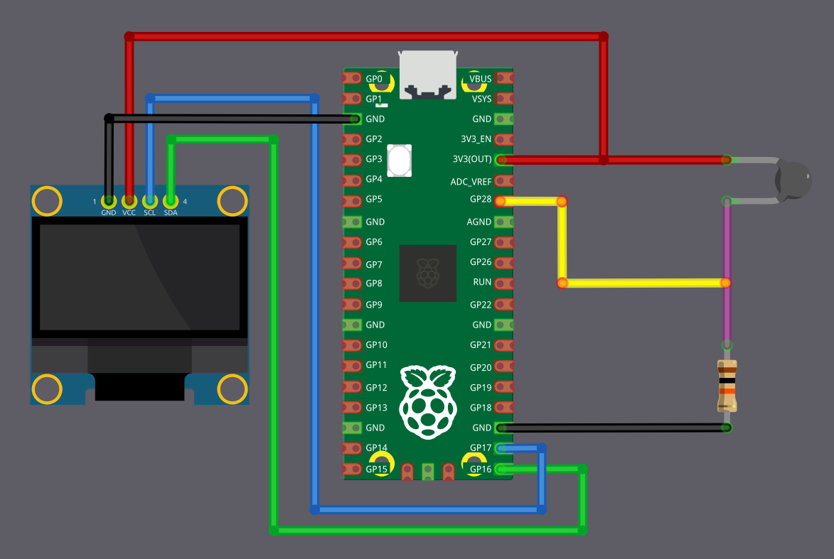
Thermistor Connection
We are going to connect the thermistor as a voltage divider and feed the divider output into an ADC pin on the Pico. Here, the thermistor acts as R1 and is connected to the 3.3 V supply, which means the ADC value decreases as the temperature increases (NTC behavior).
| Pico Pin | Wire | Component |
|---|---|---|
| 3.3 V |
|
One end of the thermistor |
| GPIO 28 (ADC2) |
|
Junction between thermistor and 10 kΩ resistor |
| 10 kΩ resistor |
|
Other end of the thermistor |
| GND |
|
Other end of the 10 kΩ resistor |
OLED (I2C) Connection
The OLED display is connected using I2C. SDA is connected to GPIO 16 and SCL is connected to GPIO 17.
| Pico Pin | Wire | OLED Pin |
|---|---|---|
| GND |
|
GND |
| 3.3 V |
|
VCC |
| GPIO 16 |
|
SDA |
| GPIO 17 |
|
SCL |
Write Embedded Rust code to Display Temperature on OLED Display
In this section, we move to the coding part. We write the code that reads the thermistor value using the ADC, converts it into temperature using the B equation, and displays the result on the OLED over I2C.
Project from Template
As usual, we are going to start by generating a new project from the template.
cargo generate --git https://github.com/ImplFerris/pico2-template.git --tag v0.3.2
When prompted, give your project a name, like “temperature-oled” and select embassy as the HAL.
Additional Crates required
We need a few additional crates to support the OLED display, format text, and mathematical operations. Add the following entries to Cargo.toml along with the existing dependencies.
#![allow(unused)]
fn main() {
ssd1306 = { version = "0.10.0", features = ["async"] }
heapless = "0.9.2"
libm = "0.2.15"
embedded-graphics = "0.8"
}-
ssd1306: Driver crate for controlling SSD1306-based OLED displays. -
heapless: In a no_std environment, Rust’s standard String type is not available because it requires heap allocation. This crate provides stack-allocated, fixed-size data structures. We use it to store formatted text such as ADC values, resistance, and temperature before sending them to the OLED. -
libm: Provides mathematical functions for no_std environments. This is required to compute the natural logarithm when using the B equation. -
embedded-graphics: The SSD1306 driver supports different ways of writing content to the display.When you use
into_buffered_graphics_mode, the display is treated like a pixel buffer. Text and shapes are first drawn into an in-memory framebuffer using the embedded-graphics API, and then the whole buffer is sent to the OLED. This mode requires the embedded-graphics crate.When you use
into_terminal_mode, the driver provides a simple text-based interface. You write characters directly to the display without drawing pixels or shapes yourself. In this case, embedded-graphics is not required.
Additional imports
#![allow(unused)]
fn main() {
// Text formatting without heap allocation
use core::fmt::Write;
use heapless::String;
// For OLED display
use ssd1306::{I2CDisplayInterface, Ssd1306Async, prelude::*};
// For ADC
use embassy_rp::adc::{Adc, Channel, Config as AdcConfig};
use embassy_rp::gpio::Pull;
// Interrupt Binding
use embassy_rp::bind_interrupts;
use embassy_rp::peripherals::I2C0;
use embassy_rp::{adc, i2c};
// I2C
use embassy_rp::i2c::{Config as I2cConfig, I2c};
// Embedded Graphics
use embedded_graphics::{
mono_font::{MonoTextStyle, iso_8859_13::FONT_7X13_BOLD},
pixelcolor::BinaryColor,
prelude::*,
text::Text,
};
}Interrupt Handler
In this project, we use both the ADC and I2C peripherals. Each of these peripherals generate interrupts, and Embassy requires that those interrupts are explicitly bound at compile time.
#![allow(unused)]
fn main() {
bind_interrupts!(struct Irqs {
ADC_IRQ_FIFO => adc::InterruptHandler;
I2C0_IRQ => i2c::InterruptHandler<I2C0>;
});
}ADC_IRQ_FIFO is the interrupt generated by the ADC when data is available in its FIFO. This interrupt is required for ADC operation in Embassy. I2C0_IRQ is the interrupt used by the I2C0 peripheral. This interrupt is required for asynchronous I2C communication with the OLED display.
Thermistor Constants
We define a few constants that describe the thermistor and ADC behavior.
#![allow(unused)]
fn main() {
const ADC_LEVELS: f64 = 4096.0;
const B_VALUE: f64 = 3950.0;
const REF_RES: f64 = 10_000.0; // Reference resistance in ohms (10 kΩ)
const REF_TEMP: f64 = 25.0; // Reference temperature 25 °C
}The thermistor we used has a resistance of 10 kΩ at 25 °C and a B value of 3950. The pico has a 12-bit ADC resolution, so 4096 possible ADC levels.
Helper functions
We will define few helper functions.
This function that converts ADC values into resistance uses the voltage divider equation. We have already covered this formula earlier, so here we simply reuse it.
#![allow(unused)]
fn main() {
// We have already covered about this formula in ADC chapter
fn adc_to_resistance(adc_value: u16, r2_res: f64) -> f64 {
let adc = adc_value as f64;
((ADC_LEVELS / adc) - 1.0) * r2_res
}
}This function that converts resistance into temperature applies the B equation. Because we are in a no_std environment, we use the libm crate to compute the natural logarithm.
#![allow(unused)]
fn main() {
// B Equation to convert resistance to temperature
fn calculate_temperature(current_res: f64, ref_res: f64, ref_temp: f64, b_val: f64) -> f64 {
let ln_value = libm::log(current_res / ref_res); // Use libm for `no_std`
let inv_t = (1.0 / ref_temp) + ((1.0 / b_val) * ln_value);
1.0 / inv_t
}
}We also define small helper functions to convert between Kelvin and Celsius.
#![allow(unused)]
fn main() {
fn kelvin_to_celsius(kelvin: f64) -> f64 {
kelvin - 273.15
}
fn celsius_to_kelvin(celsius: f64) -> f64 {
celsius + 273.15
}
}Display Setup
We configure the OLED to use I2C with SDA on GPIO 16 and SCL on GPIO 17. We set the I2C frequency to 400 kHz.
We initialize the SSD1306 display in buffered graphics mode. In this mode, all drawing operations happen in memory first. The content is sent to the OLED only when we flush the buffer. We also define the text style, you can adjust the font size.
#![allow(unused)]
fn main() {
// Display Setup
let sda = p.PIN_16;
let scl = p.PIN_17;
let mut i2c_config = I2cConfig::default();
i2c_config.frequency = 400_000; //400kHz
let i2c_bus = I2c::new_async(p.I2C0, scl, sda, Irqs, i2c_config);
let i2c_interface = I2CDisplayInterface::new(i2c_bus);
let mut display = Ssd1306Async::new(i2c_interface, DisplaySize128x64, DisplayRotation::Rotate0)
.into_buffered_graphics_mode();
display
.init()
.await
.expect("failed to initialize the display");
let text_style = MonoTextStyle::new(&FONT_7X13_BOLD, BinaryColor::On);
}ADC Setup
We configure the ADC channel connected to the thermistor pin. We then initialize the ADC peripheral using the interrupt bindings defined earlier.
#![allow(unused)]
fn main() {
// ADC Setup for thermistor
let mut adc_pin = Channel::new_pin(p.PIN_28, Pull::None);
let mut adc = Adc::new(p.ADC, Irqs, AdcConfig::default());
}Heapless String
We create a heapless string with a fixed capacity of 64 characters. This string lives on the stack and is reused on every iteration of the loop. We use it to store formatted values such as temperature, ADC reading, and resistance before drawing them on the OLED.
#![allow(unused)]
fn main() {
let mut buff: String<64> = String::new();
}Convert the Reference Temperature to Kelvin
We define the reference temperature for the thermistor as 25 °C. Since the B equation requires temperature in Kelvin, we convert this value once during initialization. This avoids repeating the conversion inside the loop.
#![allow(unused)]
fn main() {
let ref_temp = celsius_to_kelvin(REF_TEMP);
}Main Loop
In each iteration of the loop, we read the thermistor value using the ADC, convert the reading into temperature, format the result as text, and update the OLED display.
We first clear both the string buffer and the display buffer.
#![allow(unused)]
fn main() {
buff.clear();
display
.clear(BinaryColor::Off)
.expect("failed to clear the display");
}Read ADC
We then read the ADC value from the thermistor pin.
#![allow(unused)]
fn main() {
let adc_value = adc
.read(&mut adc_pin)
.await
.expect("failed to read adc value");
}Convert ADC Value to Temperature
We convert the ADC reading into resistance using the voltage divider equation. We then convert the resistance into temperature using the B equation, which gives the temperature in Kelvin. Finally, we convert the value to Celsius.
#![allow(unused)]
fn main() {
let current_res = adc_to_resistance(adc_value, REF_RES);
let temperature_kelvin = calculate_temperature(current_res, REF_RES, ref_temp, B_VALUE);
let temperature_celsius = kelvin_to_celsius(temperature_kelvin);
}Format Output Text
We format the temperature, ADC value, and resistance into the heapless string.
#![allow(unused)]
fn main() {
writeln!(buff, "Temp: {:.2} °C", temperature_celsius)
.expect("failed to format temperature");
writeln!(buff, "ADC: {}", adc_value).expect("failed to format ADC value");
writeln!(buff, "R: {:.2}", current_res).expect("failed to format Resistance");
}Update OLED Display
We draw the formatted text to the display buffer, flush the buffer to update the OLED, and wait before the next iteration.
#![allow(unused)]
fn main() {
Text::new(&buff, Point::new(5, 20), text_style)
.draw(&mut display)
.expect("Failed to write the text");
display.flush().await.expect("failed to send to display");
Timer::after_secs(2).await;
}Flash
Once you flash the firmware, you should see the temperature along with the resistance and ADC values. You can move the setup to a different room, observe how the readings change between day and night, or take it outdoors using an external power supply to see how the temperature responds in different conditions.
The full code
#![no_std]
#![no_main]
use embassy_executor::Spawner;
use embassy_rp::block::ImageDef;
use embassy_rp::{self as hal};
use embassy_time::Timer;
//Panic Handler
use panic_probe as _;
// Defmt Logging
use defmt_rtt as _;
// Text formatting without heap allocation
use core::fmt::Write;
use heapless::String;
// For OLED display
use ssd1306::{I2CDisplayInterface, Ssd1306Async, prelude::*};
// For ADC
use embassy_rp::adc::{Adc, Channel, Config as AdcConfig};
use embassy_rp::gpio::Pull;
// Interrupt Binding
use embassy_rp::bind_interrupts;
use embassy_rp::peripherals::I2C0;
use embassy_rp::{adc, i2c};
// I2C
use embassy_rp::i2c::{Config as I2cConfig, I2c};
// Embedded Graphics
use embedded_graphics::{
mono_font::{MonoTextStyle, iso_8859_13::FONT_7X13_BOLD},
pixelcolor::BinaryColor,
prelude::*,
text::Text,
};
/// Tell the Boot ROM about our application
#[unsafe(link_section = ".start_block")]
#[used]
pub static IMAGE_DEF: ImageDef = hal::block::ImageDef::secure_exe();
bind_interrupts!(struct Irqs {
ADC_IRQ_FIFO => adc::InterruptHandler;
I2C0_IRQ => i2c::InterruptHandler<I2C0>;
});
const ADC_LEVELS: f64 = 4096.0;
const B_VALUE: f64 = 3950.0;
const REF_RES: f64 = 10_000.0; // Reference resistance in ohms (10 kΩ)
const REF_TEMP: f64 = 25.0; // Reference temperature 25 °C
// We have already covered about this formula in ADC chpater
fn adc_to_resistance(adc_value: u16, r2_res: f64) -> f64 {
let adc = adc_value as f64;
((ADC_LEVELS / adc) - 1.0) * r2_res
}
// B Equation to convert resistance to temperature
fn calculate_temperature(current_res: f64, ref_res: f64, ref_temp: f64, b_val: f64) -> f64 {
let ln_value = libm::log(current_res / ref_res); // Use libm for `no_std`
let inv_t = (1.0 / ref_temp) + ((1.0 / b_val) * ln_value);
1.0 / inv_t
}
fn kelvin_to_celsius(kelvin: f64) -> f64 {
kelvin - 273.15
}
fn celsius_to_kelvin(celsius: f64) -> f64 {
celsius + 273.15
}
#[embassy_executor::main]
async fn main(_spawner: Spawner) {
let p = embassy_rp::init(Default::default());
// Display Setup
let sda = p.PIN_16;
let scl = p.PIN_17;
let mut i2c_config = I2cConfig::default();
i2c_config.frequency = 400_000; //400kHz
let i2c_bus = I2c::new_async(p.I2C0, scl, sda, Irqs, i2c_config);
let i2c_interface = I2CDisplayInterface::new(i2c_bus);
let mut display = Ssd1306Async::new(i2c_interface, DisplaySize128x64, DisplayRotation::Rotate0)
.into_buffered_graphics_mode();
display
.init()
.await
.expect("failed to initialize the display");
let text_style = MonoTextStyle::new(&FONT_7X13_BOLD, BinaryColor::On);
// ADC Setup for thermistor
let mut adc_pin = Channel::new_pin(p.PIN_28, Pull::None);
let mut adc = Adc::new(p.ADC, Irqs, AdcConfig::default());
let mut buff: String<64> = String::new();
let ref_temp = celsius_to_kelvin(REF_TEMP);
loop {
buff.clear();
display
.clear(BinaryColor::Off)
.expect("failed to clear the display");
let adc_value = adc
.read(&mut adc_pin)
.await
.expect("failed to read adc value");
let current_res = adc_to_resistance(adc_value, REF_RES);
let temperature_kelvin = calculate_temperature(current_res, REF_RES, ref_temp, B_VALUE);
let temperature_celsius = kelvin_to_celsius(temperature_kelvin);
writeln!(buff, "Temp: {:.2} °C", temperature_celsius)
.expect("failed to format temperature");
writeln!(buff, "ADC: {}", adc_value).expect("failed to format ADC value");
writeln!(buff, "R: {:.2}", current_res).expect("failed to format Resistance");
Text::new(&buff, Point::new(5, 20), text_style)
.draw(&mut display)
.expect("Failed to write the text");
display.flush().await.expect("failed to send to display");
Timer::after_secs(2).await;
}
}
// Program metadata for `picotool info`.
// This isn't needed, but it's recommended to have these minimal entries.
#[unsafe(link_section = ".bi_entries")]
#[used]
pub static PICOTOOL_ENTRIES: [embassy_rp::binary_info::EntryAddr; 4] = [
embassy_rp::binary_info::rp_program_name!(c"temperature-oled"),
embassy_rp::binary_info::rp_program_description!(c"your program description"),
embassy_rp::binary_info::rp_cargo_version!(),
embassy_rp::binary_info::rp_program_build_attribute!(),
];
// End of fileClone the existing project
You can clone (or refer) project I created and navigate to the temperature-oled folder.
git clone https://github.com/ImplFerris/pico2-embassy-projects
cd pico2-embassy-projects/temperature-oled/
USB Serial Communication
In this section, we are going to set up communication between our device (Pico) and a computer running Linux. We will send a simple string from the Pico to the computer, and we will also send input from the computer back to the Pico.
This is especially useful when you do not have a debug probe and want to print sensor readings or status messages to the system console to quickly see what is going on. I have personally used this approach many times before I actually bought a debug probe.
Tip
If you are using a debug probe, you can skip this chapter for now. You can always come back to it later when you want to exchange data with a computer using USB, such as sending messages, reading input, or building simple command based interfaces.
CDC ACM
When you plug a USB device into a computer, the computer needs to know what kind of device it is and how to talk to it. USB solves this by defining standard device types, called classes.
CDC stands for Communication Device Class. It is a USB class meant for devices that communicate by sending and receiving data, similar to serial communication. One very common CDC type is called ACM, which stands for Abstract Control Model.
CDC ACM makes a USB device look like a simple serial port to the computer.
So even though the data is traveling over USB, the operating system treats it like a normal serial connection. On Linux, this is why the device shows up as something like /dev/ttyACM0.
If you have ever used UART with a USB to serial adapter, this feels almost exactly the same from the software side.
Tools for Linux
When you flash the code in this exercise, the device will appear as /dev/ttyACM0 on your computer. To interact with the USB serial port on Linux, you can use tools like minicom, tio (or cat) to read and send data to and from the device
- minicom: Minicom is a text-based serial port communications program. It is used to talk to external RS-232 devices such as mobile phones, routers, and serial console ports.
- tio: tio is a serial device tool which features a straightforward command-line and configuration file interface to easily connect to serial TTY devices for basic I/O operations.
Rust Crates
We will be using the example taken from the RP-HAL repository. It uses two crates: usb-device, an USB stack for embedded devices in Rust, and usbd-serial, which implements the USB CDC-ACM serial port class. The SerialPort class in usbd-serial implements a stream-like buffered serial port and can be used in a similar way to UART.
References
- CDC: Communication Device Class (ACM)
- USB Device CDC ACM Class
- What is the difference between /dev/ttyUSB and /dev/ttyACM?
- Defined Class Codes
C 实现
USB Serial Logging with Embassy on Raspberry Pi Pico
In this chapter, we will look at a simple way to log messages from the Raspberry Pi Pico to the system console using USB serial. We will use the USB interface along with the embassy-usb-logger crate to send log output to the host.
We will keep the example intentionally small. The Pico maintains a counter that increments once every second. Each time the value changes, we print it to the system console over USB. When the counter reaches its limit, it wraps back to zero and continues. The goal here is not the counter itself, but to show how logging works when USB serial is used as the output.
This approach is useful when you want log output to appear as a regular serial device on your computer. Once this is set up, you can use the same logging method to print sensor values, state changes, or debug messages from your application.
Project from template
We will start by generating a new project using the template.
cargo generate --git https://github.com/ImplFerris/pico2-template.git --tag v0.3.2
When prompted, give your project a name, for example “cdc-logger”, and select embassy as the HAL. You do not need to enable defmt for this setup.
Additional crates required
Update your Cargo.toml to include the USB logger crate.
embassy-usb-logger = "0.5.1"
log = "0.4"
The embassy-usb-logger crate provides a ready to use logger implementation that sends log messages over USB. The log crate provides the logging macros used throughout the program.
Additional imports
Add the following imports to your main.rs file.
#![allow(unused)]
fn main() {
// For USB
use embassy_rp::{peripherals::USB, usb};
}USB interrupt binding
The USB peripheral requires an interrupt handler. Embassy provides the handler, and we only need to bind it.
#![allow(unused)]
fn main() {
embassy_rp::bind_interrupts!(struct Irqs {
USBCTRL_IRQ => usb::InterruptHandler<USB>;
});
}USB logger task
USB handling runs in its own task. This task creates the USB driver and starts the USB logger.
#![allow(unused)]
fn main() {
#[embassy_executor::task]
async fn logger_task(usb: embassy_rp::Peri<'static, embassy_rp::peripherals::USB>) {
let driver = embassy_rp::usb::Driver::new(usb, Irqs);
embassy_usb_logger::run!(1024, log::LevelFilter::Info, driver);
}
}The logger task runs continuously and handles all USB communication in the background.
Main function
In the main function, we spawn the USB logger task.
#![allow(unused)]
fn main() {
spawner.must_spawn(logger_task(p.USB));
}Main loop
We keep a simple counter and increase it once every second. The counter uses wrapping arithmetic, so after reaching its maximum value it rolls back to zero. On each iteration, we log the current value using log::info!, which sends the message over USB serial.
#![allow(unused)]
fn main() {
let mut i: u8 = 0;
loop {
i = i.wrapping_add(1);
log::info!("USB says: {}", i);
Timer::after_secs(1).await;
}
}Clone the existing project
You can clone (or refer) project I created and navigate to the cdc-logger folder.
git clone https://github.com/ImplFerris/pico2-embassy-projects
cd pico2-embassy-projects/usb-serial/cdc-logger/
How to Run?
The method to flash (run the code) on the Pico is the same as usual. However, we need to set up tio to interact with the Pico through the serial port (/dev/ttyACM0). This allows us to read data from the Pico or send data to it.
tio
Make sure you have tio installed on your system. If not, you can install it using:
apt install tio
Connecting to the Serial Port
Run the following command to connect to the Pico’s serial port:
tio /dev/ttyACM0
This will open a terminal session for communicating with the Pico.
Flashing and Running the Code
Open another terminal, navigate to the project folder, and flash the code onto the Pico as usual:
cargo run --release
Once the program starts running, you should see the counter value printed once every second in the tio terminal.
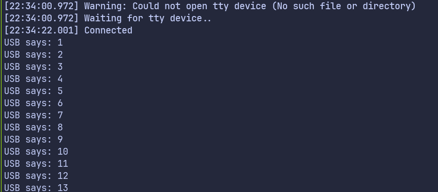
Reference
rp-usb-console- a crate that does USB logging, but also supports commands e.g. to configure log levels
USB Serial Example Using rp-hal
We are going to use an example provided in the RP HAL repository and make a few small changes to it so we can clearly see two way communication working.
The original example sends a simple “Hello, World!” message from the Pico to the computer once the internal timer reaches a certain count. It also polls for incoming data from the computer and sends data back.
We’ll slightly modify the code to make it more fun. Instead of sending “Hello, World!”, we’ll send “Hello, Rust!” to the computer. Wait, I know that’s not the fun part. Here it comes: if you type ‘r’ in the terminal connected via USB serial, the onboard LED will turn on. Type anything else, and the LED will turn off.
Project from template
To set up the project, generate it from the provided template:
cargo generate --git https://github.com/ImplFerris/pico2-template.git --tag v0.3.2
When prompted, give your project a name, like “usb-serial-led” and select RP-HAL as the HAL.
Additional Crates required
Update your Cargo.toml to add the following crates along with the existing dependencies:
#![allow(unused)]
fn main() {
usbd-serial = "0.2.2"
usb-device = "0.3.2"
}Additional imports
#![allow(unused)]
fn main() {
// USB Device support
use usb_device::{class_prelude::*, prelude::*};
// USB Communications Class Device support
use usbd_serial::SerialPort;
// For the LED
use embedded_hal::digital::OutputPin;
}LED Setup
We will configure the onboard LED.
#![allow(unused)]
fn main() {
let mut led = pins.gpio25.into_push_pull_output();
}Set up the USB driver
We first create the USB bus using the RP2350 USB peripheral and its DPRAM:
#![allow(unused)]
fn main() {
let usb_bus = UsbBusAllocator::new(hal::usb::UsbBus::new(
pac.USB,
pac.USB_DPRAM,
clocks.usb_clock,
true,
&mut pac.RESETS,
));
}Creating the CDC ACM Serial Interface
Next, we create a CDC ACM serial port on top of the USB bus:
#![allow(unused)]
fn main() {
let mut serial = SerialPort::new(&usb_bus);
}This serial object behaves very similarly to a UART style serial port.
Creating the USB Device
Now we describe the USB device itself so the host knows how to enumerate it:
#![allow(unused)]
fn main() {
let mut usb_dev = UsbDeviceBuilder::new(&usb_bus, UsbVidPid(0x16c0, 0x27dd))
.strings(&[StringDescriptors::default()
.manufacturer("implRust")
.product("Ferris")
.serial_number("TEST")])
.unwrap()
.device_class(2) // 2 for the CDC, from: https://www.usb.org/defined-class-codes
.build();
}We use a fake VID and PID for development, provide basic string descriptors, and set the device class to CDC so Linux treats it as a serial device.
Tracking the Greeting Message
We declare a flag to track whether the greeting message has already been sent. This flag is checked inside the main loop to ensure the message is sent only once.
#![allow(unused)]
fn main() {
let mut said_hello = false;
}Main Loop
Sending Message to PC
Once the program is running, we check the timer. When the counter reaches 2,000,000 ticks, we send a message “Hello, Rust!” to the computer and make sure it is sent only once:
#![allow(unused)]
fn main() {
if !said_hello && timer.get_counter().ticks() >= 2_000_000 {
said_hello = true;
// Writes bytes from `data` into the port and returns the number of bytes written.
let _ = serial.write(b"Hello, Rust!\r\n");
}
}Polling for data
At the same time, we continuously poll the USB device for incoming data. When data arrives, we read it and inspect each received byte. If the character is ‘r’, the onboard LED is turned on. Any other character turns the LED off:
#![allow(unused)]
fn main() {
if usb_dev.poll(&mut [&mut serial]) {
let mut buf = [0u8; 64];
if let Ok(count) = serial.read(&mut buf) {
for &byte in &buf[..count] {
if byte == b'r' {
led.set_high().expect("unable to turn on LED");
} else {
led.set_low().expect("unable to turn off LED");
}
}
}
}
}The Full code
#![no_std]
#![no_main]
use embedded_hal::delay::DelayNs;
use hal::block::ImageDef;
use rp235x_hal as hal;
//Panic Handler
use panic_probe as _;
// USB Device support
use usb_device::{class_prelude::*, prelude::*};
// USB Communications Class Device support
use usbd_serial::SerialPort;
// For the LED
use embedded_hal::digital::OutputPin;
/// Tell the Boot ROM about our application
#[unsafe(link_section = ".start_block")]
#[used]
pub static IMAGE_DEF: ImageDef = hal::block::ImageDef::secure_exe();
/// External high-speed crystal on the Raspberry Pi Pico 2 board is 12 MHz.
/// Adjust if your board has a different frequency
const XTAL_FREQ_HZ: u32 = 12_000_000u32;
#[hal::entry]
fn main() -> ! {
// Grab our singleton objects
let mut pac = hal::pac::Peripherals::take().unwrap();
// Set up the watchdog driver - needed by the clock setup code
let mut watchdog = hal::Watchdog::new(pac.WATCHDOG);
// Configure the clocks
//
// The default is to generate a 125 MHz system clock
let clocks = hal::clocks::init_clocks_and_plls(
XTAL_FREQ_HZ,
pac.XOSC,
pac.CLOCKS,
pac.PLL_SYS,
pac.PLL_USB,
&mut pac.RESETS,
&mut watchdog,
)
.ok()
.unwrap();
// The single-cycle I/O block controls our GPIO pins
let sio = hal::Sio::new(pac.SIO);
// Set the pins up according to their function on this particular board
let pins = hal::gpio::Pins::new(
pac.IO_BANK0,
pac.PADS_BANK0,
sio.gpio_bank0,
&mut pac.RESETS,
);
let timer = hal::Timer::new_timer0(pac.TIMER0, &mut pac.RESETS, &clocks);
let mut led = pins.gpio25.into_push_pull_output();
let usb_bus = UsbBusAllocator::new(hal::usb::UsbBus::new(
pac.USB,
pac.USB_DPRAM,
clocks.usb_clock,
true,
&mut pac.RESETS,
));
let mut serial = SerialPort::new(&usb_bus);
let mut usb_dev = UsbDeviceBuilder::new(&usb_bus, UsbVidPid(0x16c0, 0x27dd))
.strings(&[StringDescriptors::default()
.manufacturer("implRust")
.product("Ferris")
.serial_number("TEST")])
.unwrap()
.device_class(2) // 2 for the CDC, from: https://www.usb.org/defined-class-codes
.build();
let mut said_hello = false;
loop {
if !said_hello && timer.get_counter().ticks() >= 2_000_000 {
said_hello = true;
// Writes bytes from `data` into the port and returns the number of bytes written.
let _ = serial.write(b"Hello, Rust!\r\n");
}
if usb_dev.poll(&mut [&mut serial]) {
let mut buf = [0u8; 64];
if let Ok(count) = serial.read(&mut buf) {
for &byte in &buf[..count] {
if byte == b'r' {
led.set_high().expect("unable to turn on LED");
} else {
led.set_low().expect("unable to turn off LED");
}
}
}
}
}
}
// Program metadata for `picotool info`.
// This isn't needed, but it's recommended to have these minimal entries.
#[unsafe(link_section = ".bi_entries")]
#[used]
pub static PICOTOOL_ENTRIES: [hal::binary_info::EntryAddr; 5] = [
hal::binary_info::rp_cargo_bin_name!(),
hal::binary_info::rp_cargo_version!(),
hal::binary_info::rp_program_description!(c"your program description"),
hal::binary_info::rp_cargo_homepage_url!(),
hal::binary_info::rp_program_build_attribute!(),
];
// End of fileClone the existing project
You can clone (or refer) project I created and navigate to the usb-serial-led folder.
git clone https://github.com/ImplFerris/pico2-rp-projects
cd pico2-projects/usb-serial-led/
How to Run ?
The method to flash (run the code) on the Pico is the same as usual. However, we need to set up tio to interact with the Pico through the serial port (/dev/ttyACM0). This allows us to read data from the Pico or send data to it.
tio
Make sure you have tio installed on your system. If not, you can install it using:
apt install tio
Connecting to the Serial Port
Run the following command to connect to the Pico’s serial port:
tio /dev/ttyACM0
This will open a terminal session for communicating with the Pico.
Flashing and Running the Code
Open another terminal, navigate to the project folder, and flash the code onto the Pico as usual:
cargo run
If everything is set up correctly, you should see a “Connected” message in the tio terminal, followed by the “Hello, Rust!” message sent from the Pico.
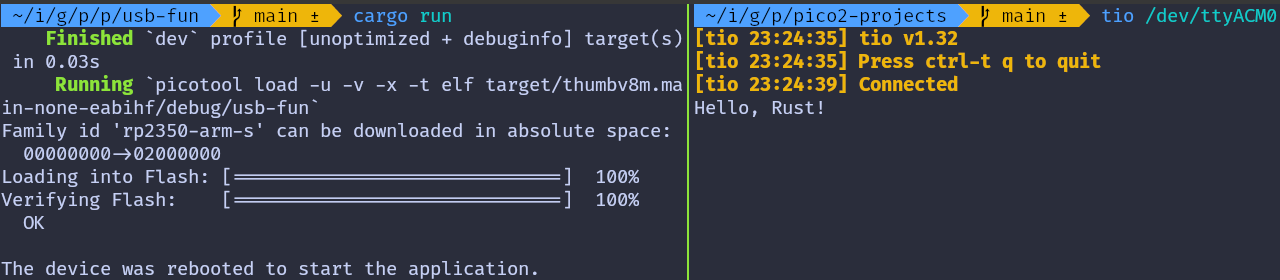
Send data to Pico
In the terminal where tio is running, you type that will be sent to the Pico. You won’t see what you type (since we’re not echoing back the input).
If you press the letter ‘r’, the onboard LED will be turned on. If you press any other character, the LED will be turned off.
Embassy version
You can also refer to this project, which demonstrates using USB Serial with the Embassy framework.
git clone https://github.com/ImplFerris/pico2-embassy-projects
cd pico2-embassy-projects/usb-serial/
Serial Peripheral Interface (SPI)
In this section, we will learn what SPI is and how to use the SPI communication buses of the Raspberry Pi Pico.
What is SPI?
SPI stands for Serial Peripheral Interface. It is one of the most common ways for microcontrollers to communicate with devices like displays, sensors, and SD Cards. Technically, it is called as a serial, full duplex, and synchronous interface. But what do those terms mean?
-
Serial means data is sent one bit at a time, one after another, over a single data line. This is different from parallel communication, where multiple bits are sent at the same time using multiple data lines.
-
Full duplex means two devices can send and receive data at the same time. Both devices can transmit to each other simultaneously without waiting for the other to finish. This is different from half duplex, where devices must take turns: one sends while the other receives.
-
Synchronous means both devices use a shared clock signal. This clock defines exactly when each bit of data is sent and read, so both sides stay aligned during communication.
Controller and Peripheral
SPI uses a controller-peripheral model (previously called master-slave). The controller is the device that starts the communication and provides the clock signal. The peripheral is the device that responds to the controller.
In our case, the Raspberry Pi Pico acts as the controller, and devices like displays, sensors, or SD Cards are peripherals.

Figure: Single SPI bus with a controller and a single peripheral
The connection typically uses four lines:
-
The SCK (Serial Clock) line carries the clock signal generated by the controller. This signal keeps both the controller and the device in sync during data transfer.
-
The MOSI (Master Out, Slave In) line is used to send data from the controller to the device. In some datasheets, this line may be labeled as SDO (Serial Data Out).
-
The MISO (Master In, Slave Out) line carries data from the device to the controller. It may also be referred to as SDI (Serial Data In) depending on the device.
-
Finally, the CS (Chip Select) line is used by the controller to choose which device it wants to communicate with. Each connected device usually has its own dedicated CS line. When the controller pulls a device’s CS line low(active), that device becomes active and ready to communicate. In some older documentation, this line may be referred to as SS (Slave Select).

Figure: Single SPI bus with a controller and multiple peripherals
SPI Modes
SPI supports four modes, numbered from 0 to 3. These decide when data is read and written depending on the clock’s idle level and edge.
Don’t worry too much about the details right now. Mode 0 is the most common and works with most devices.
Why SPI?
SPI is a great choice when you want fast and reliable communication between your microcontroller and a peripheral. It’s much faster than I²C or UART, simple to use, and allows data to be sent and received at the same time (full-duplex). This makes it ideal for high-speed devices like displays or SD cards.
As long as you have enough GPIO pins and don’t need to connect a large number of devices, SPI is usually the best tool for the job.
Resources
For more in-depth technical details, refer these
Using SPI with Embedded Rust Ecosystem
In the previous section, we learned what SPI is and how the controller-peripheral model works. Now, let’s see how these concepts apply within the Embedded Rust ecosystem.
Rust’s embedded ecosystem is designed to be modular and reusable. This means you can write code for one microcontroller and reuse it on another with minimal changes. One key to this flexibility is the use of traits defined by the embedded-hal crate.
SPI in embedded-hal
The embedded-hal crate defines standard traits for working with SPI, so that drivers and libraries can be written generically. Two important traits for SPI are:
-
SpiBus: Represents full control over the SPI bus, including the SCK, MOSI, and MISO lines. This must be implemented by the microcontroller’s HAL crate. For example, the esp-hal crate implements SpiBus. If you are curious, you can look at the implementation here.
-
SpiDevice: Represents access to a single SPI device that may share the bus with others. It takes control of the chip select (CS) pin and ensures the device is properly selected before communication and released afterward.
Platform-Independent Drivers
Imagine you are writing a driver for a sensor or a display that communicates over SPI. You don’t want to tie your code to a specific microcontroller like the Raspberry Pi Pico or ESP32. Instead, you can write the driver in a generic way using the embedded-hal traits.
As long as your driver only depends on the SpiDevice or SpiBus traits, it can run on any platform that provides an implementation of these traits-such as STM32, nRF, or ESP32.
Sharing the SPI Bus
In many projects, multiple SPI devices share the same SPI bus. For example, you might have a display, an SD card, and a temperature sensor all connected to the same MOSI, MISO, and SCK lines. The only thing that separates them is their chip select (CS) pin.
r

Figure: Single SPI bus with a controller and multiple peripherals
If you give full control of the SPI bus to just one driver (using SpiBus), the others can’t use it. Instead, we need a way to share the SPI bus safely across multiple devices.
That’s where SpiDevice comes in - it allows each driver to use only its own CS pin, while still sharing the underlying bus.
In practice, this means we need to pass a struct that implements SpiDevice to each driver, rather than giving them the full bus.
How do we get a SpiDevice?
We said that each driver should be given a SpiDevice implementation instead of the full SpiBus. But are we supposed to write this SpiDevice struct ourselves?
Not really. While it’s possible to write your own implementation, it’s usually unnecessary-and can be tricky to get right, especially when multiple devices need to coordinate bus access.
That’s where the embedded-hal-bus crate comes in. It provides ready-to-use wrappers that implement the SpiDevice trait for you. These wrappers handle bus access, chip select control, and optional synchronization between devices.

-
If your project only uses one SPI device and doesn’t need sharing, you can use the
ExclusiveDevicestruct - it gives exclusive access to the bus for one device. -
But if your project has multiple SPI devices sharing the same bus, you can choose one of the shared access implementations such as
AtomicDeviceorCriticalSectionDevice. These manage access to the bus so that each device gets a turn without interfering with the others.
These structs allow you to focus on using or building drivers without worrying about low-level coordination or writing boilerplate code.
Resources
- embedded-hal docs on SPI: This documentation provides in-depth details on how SPI traits are structured and how they are intended to be used across different platforms.
RP2350 SPI Peripherals
The RP2350 includes two SPI controllers, named SPI0 and SPI1. Both are general purpose peripherals and are available for application use. These controllers provide flexible serial communication capabilities for connecting external devices like sensors, displays, SD cards, and other SPI peripherals.
Each SPI peripheral supports standard SPI operation, including master and slave modes, full-duplex transfers, and the usual SPI signals: SCLK, MOSI, MISO, and chip select.
You can refer to the 1046th page on the RP2350 datasheet for more detailed and accurate information: https://pip-assets.raspberrypi.com/categories/1214-rp2350/documents/RP-008373-DS-2-rp2350-datasheet.pdf?disposition=inline#page=1047
GPIO Pins
The Raspberry Pi Pico 2 exposes two SPI buses on its GPIO header: SPI0 and SPI1. Each SPI bus uses four signals: clock (SCK), transmit (MOSI), receive (MISO), and chip select (CS).
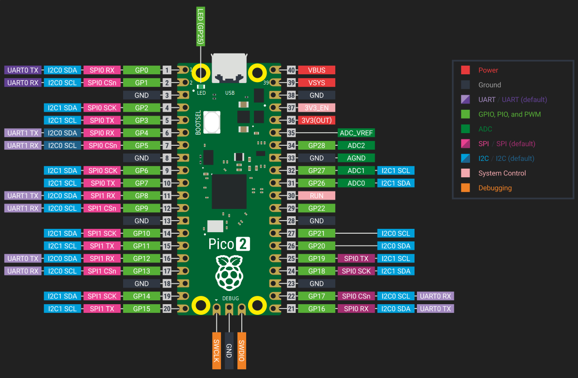
In the above diagram, the SPI pins are highlighted in pink.
SPI0 pin options
| MISO (RX) | CS | SCK | MOSI (TX) |
|---|---|---|---|
| GPIO 0 | GPIO 1 | GPIO 2 | GPIO 3 |
| GPIO 4 | GPIO 5 | GPIO 6 | GPIO 7 |
| GPIO 16 | GPIO 17 | GPIO 18 | GPIO 19 |
SPI1 pin options
| MISO (RX) | CS | SCK | MOSI (TX) |
|---|---|---|---|
| GPIO 8 | GPIO 9 | GPIO 10 | GPIO 11 |
| GPIO 12 | GPIO 13 | GPIO 14 | GPIO 15 |
Using SPI in embassy
Embassy provides two ways to use SPI. One is async, where transfers can be awaited without blocking the executor. The other is blocking, which behaves more like traditional HALs and is often simpler for small examples or one-off transfers.
Async mode
In async mode, SPI uses DMA under the hood. You must provide DMA channels, and all transfers are performed using .await. This is useful when SPI transfers are part of a larger async application and you do not want to block other tasks.
#![allow(unused)]
fn main() {
let miso = p.PIN_12;
let mosi = p.PIN_11;
let clk = p.PIN_10;
let mut spi_bus = Spi::new(p.SPI1, clk, mosi, miso, p.DMA_CH0, p.DMA_CH1, spi::Config::default());
let tx_buf = [1_u8, 2, 3, 4, 5, 6];
let mut rx_buf = [0_u8; 6];
spi_bus.transfer(&mut rx_buf, &tx_buf).await.unwrap();
info!("{:?}", rx_buf);
}Here, data is written from tx_buf while data received from the peripheral is stored in rx_buf. The call to transfer only returns once the SPI transaction is complete.
Blocking mode
Blocking SPI is simpler, calls return only after the transfer is finished, and no DMA or async context is required.
#![allow(unused)]
fn main() {
let miso = p.PIN_12;
let mosi = p.PIN_11;
let clk = p.PIN_10;
let mut config = spi::Config::default();
let mut spi_bus = Spi::new_blocking(p.SPI1, clk, mosi, miso, config);
spi_bus.blocking_transfer_in_place(&mut buf).unwrap();
}Using SPI in rp-hal
In the rp-hal SPI, you need to first configure the pins into SPI function mode, then the SPI peripheral is created and initialized with the desired clock speed and SPI mode.
#![allow(unused)]
fn main() {
// These are implicitly used by the spi driver if they are in the correct mode
let spi_mosi = pins.gpio7.into_function::<hal::gpio::FunctionSpi>();
let spi_miso = pins.gpio4.into_function::<hal::gpio::FunctionSpi>();
let spi_sclk = pins.gpio6.into_function::<hal::gpio::FunctionSpi>();
let spi_bus = hal::spi::Spi::<_, _, _, 8>::new(pac.SPI0, (spi_mosi, spi_miso, spi_sclk));
// Exchange the uninitialised SPI driver for an initialised one
let mut spi_bus = spi_bus.init(
&mut pac.RESETS,
clocks.peripheral_clock.freq(),
16.MHz(),
embedded_hal::spi::MODE_0,
);
// Write out 0, ignore return value
if spi_bus.write(&[0]).is_ok() {
// SPI write was successful
};
}Example Driver Usage
Usually, you will not talk to SPI directly. Instead, you pass an SPI device to a driver. This usually means creating an SPI bus first, then wrapping it using ExclusiveDevice provided by the embedded-hal-bus crate.
#![allow(unused)]
fn main() {
let clk = p.PIN_14;
let mosi = p.PIN_15;
let spi_bus = Spi::new_blocking_txonly(p.SPI1, clk, mosi, SpiConfig::default());
let spi_dev = ExclusiveDevice::new_no_delay(spi_bus, cs_pin).expect("Failed to get exclusive device");
// Create a display instance for a single 8x8 LED matrix (not daisy-chained)
let mut display = SingleMatrix::from_spi(spi_dev).expect("display count 1 should not panic");
}C 实现
MAX7219 8X8 Dot LED Matrix Display Module
In this chapter, we are going to work with one of the interesting display modules. It is an 8×8 Dot LED Matrix. An LED Dot Matrix is basically a grid of LEDs arranged in rows and columns that lets you display patterns, numbers, text, and simple graphics. The module we are working with is an 8×8 matrix, which gives us 64 individual LEDs to control.
Dot matrix displays are commonly used in everyday places. You can see them in buses and trains for route numbers and arrival messages, in elevators for floor numbers and direction arrows, and in digital clocks for time and basic symbols. They are also used on industrial machines and control panels to show operating status, warnings, or error messages, and in mall and arcade games.
Meet the Hardware
Now we are going to look at the hardware itself. The module is built around a chip called the MAX7219. This chip is responsible for driving all 64 LEDs in the 8x8 matrix.
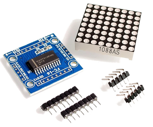
Without this chip, you would need many GPIO pins because each row and column of the LED matrix would have to be connected and controlled directly by the microcontroller. The MAX7219 takes care of that internally, so the microcontroller only needs to send high level commands instead of managing every LED.
Tip
In this book, we will not look at the internal working of the MAX7219. We will use an existing driver and focus on controlling the display. If you want to learn how to build a MAX7219 driver from scratch, including implementing the embedded-graphics trait, you can find that in the RED (Rust Embedded Drivers) book.
Daisy Chaining
One useful feature of the MAX7219 is that modules can be daisy chained. This means you can connect multiple identical modules together to form a larger display. For example, you can connect 4 or 8 modules side by side to create a wider dot matrix.
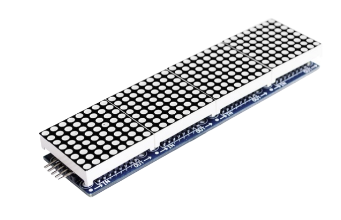
Some modules come with headers already soldered to make chaining easier. When using multiple modules, you need to be careful with wiring and power, since more LEDs means higher current draw. We will start with a single module and keep things simple.
7-Segment Displays
The same MAX7219 chip is also commonly used with 7-segment LED displays. The internal working and communication method are the same. In this chapter, we will focus only on the 8x8 LED matrix. Once you understand this, working with 7-segment displays will feel very similar.

Communication
The MAX7219 uses a serial interface that is similar to SPI. It needs three control signals. DIN is the data line used to send information to the chip. CLK is the clock signal that tells the chip when to read each bit. CS, sometimes labeled LOAD, is used to latch the data into the chip.
On the microcontroller side, we use the SPI peripheral in a write only manner to send data to the MAX7219. The chip does not send any data back. It only receives commands and updates the display based on what we send.
Circuit
The MAX7219 display requires five connections to the Raspberry Pi Pico 2. This example uses SPI1 with GPIO 13, 14, and 15, but you can use any valid SPI pin set on your Pico.
| Pico Pin | Wire | MAX7219 Pin |
|---|---|---|
| GPIO 13 (SPI1 CS) |
|
CS / LOAD |
| GPIO 14 (SPI1 SCK) |
|
CLK |
| GPIO 15 (SPI1 MOSI) |
|
DIN |
| VBUS (5 V) |
|
VCC |
| GND |
|
GND |
C 实现
Embedded Rust Code to Control MAX7219 LED Matrix on Raspberry Pi Pico 2
Let us move on to the coding part. In this program, we will draw a square on the 8x8 LED matrix using embedded-graphics.
Tip
Drawing a square is just an example, but once you learn the basics, you can do much more with it. You can scroll text, display icons or smilies, and even animate objects. You can check out the examples here: https://github.com/ImplFerris/max7219-examples. You can also try building a simple clock using daisy-chained matrices.
As usual, create a new project using the provided template.
#![allow(unused)]
fn main() {
cargo generate --git https://github.com/ImplFerris/pico2-template.git --tag v0.3.2
}When prompted, give your project a name, like “hello-max7219” and select embassy as the HAL.
Additional crates
We will add the following crates along with existing dependencies
max7219-display = { version = "0.1.5", features = ["led-matrix", "graphics"] }
embedded-graphics = "0.8.0"
embedded-hal-bus = "0.3.0"
The max7219-display crate provides the driver used in this program. The driver supports different kinds of display modules, such as 7-segment displays and LED matrices. In our case, we are using an 8x8 LED matrix, so we enable the led-matrix feature. Since we want to draw shapes instead of manually controlling individual LEDs, we also enable the graphics feature, which implements the embedded-graphics traits for the driver.
The embedded-graphics crate is used to create shapes and text in a structured way. It provides primitives like rectangles, points, and styles, which makes drawing on the LED matrix much easier.
embedded-hal-bus
The embedded-hal crate defines common traits for peripherals like SPI, enabling drivers to work across different microcontrollers. To understand why embedded-hal-bus is needed, it helps to look at how these traits are organized.
Embedded HAL separates SPI into two distinct concepts: the SPI bus (representing the shared clock and data lines) and the SPI device (representing a single peripheral with its own chip select line). Microcontroller HALs typically provide an SPI bus implementation, but device drivers are written to work with SPI devices.
The embedded-hal-bus crate bridges this gap. It provides adapters that wrap an SPI bus and manage the chip select pin, creating the SPI device interface that drivers expect. In this chapter, we use ExclusiveDevice, the simplest adapter. It’s designed for scenarios where only one device uses the SPI bus, it automatically asserts the chip select at the start of each transaction and deasserts it when complete.
Additional Imports
We now add the imports needed for SPI, the MAX7219 display driver, and drawing with embedded-graphics.
#![allow(unused)]
fn main() {
// For MAX7219
use embedded_hal_bus::spi::ExclusiveDevice;
use max7219_display::led_matrix::display::SingleMatrix;
// For Drawing shapes
use embedded_graphics::pixelcolor::BinaryColor;
use embedded_graphics::prelude::*;
use embedded_graphics::primitives::{PrimitiveStyleBuilder, Rectangle};
// For SPI
use embassy_rp::spi::{Config as SpiConfig, Spi};
// For CS Pin
use embassy_rp::gpio::{Level, Output};
}SPI setup and chip select
Let’s start by creating the chip select pin. The MAX7219 uses an active-low chip select line, so we initialize the pin in the high state. This keeps the device inactive until an SPI transfer begins.
#![allow(unused)]
fn main() {
let cs_pin = Output::new(p.PIN_13, Level::High);
}Next, we assign the SPI clock and MOSI pins. Since the MAX7219 is a write-only device, only these two signals are required. There is no MISO pin involved in this setup.
#![allow(unused)]
fn main() {
let clk = p.PIN_14;
let mosi = p.PIN_15;
}With the pins selected, we create the SPI peripheral. We use a transmit-only blocking SPI instance since all communication goes from the Pico to the display.
#![allow(unused)]
fn main() {
let spi_bus = Spi::new_blocking_txonly(p.SPI1, clk, mosi, SpiConfig::default());
}At this point, we have an SPI bus, but it does not yet manage chip select. To handle that, we wrap the bus using ExclusiveDevice. This turns the SPI bus into an SPI device by automatically controlling the chip select pin for each transfer.
#![allow(unused)]
fn main() {
let spi_dev =
ExclusiveDevice::new_no_delay(spi_bus, cs_pin).expect("Failed to get exclusive device");
}After this step, the SPI device is ready to be used by the MAX7219 display driver.
Creating the display instance
With the SPI device ready, we now create the LED matrix display instance. Here we are working with a single 8x8 LED matrix, not a daisy-chained setup. The display driver takes ownership of the SPI device and uses it to send commands and pixel data to the MAX7219.
#![allow(unused)]
fn main() {
// Create a display instance for a single 8x8 LED matrix (not daisy-chained)
let mut display = SingleMatrix::from_spi(spi_dev).expect("display count 1 should not panic");
}Setting the display brightness
After creating the display instance, we set the brightness level. The MAX7219 supports multiple intensity levels, and here we configure it for the only device at index 0. A low intensity value is usually sufficient and avoids excessive brightness.
#![allow(unused)]
fn main() {
// Set brightness (intensity level) of the only device at index 0
display
.driver()
.set_intensity(0, 1)
.expect("failed to set intensity");
}Drawing a rectangle
Now we draw a simple shape using embedded-graphics. Instead of filling the entire area, we draw a hollow rectangle so only the border pixels are turned on. I first tried a filled rectangle, but it did not look good, so I have commented out that version.
First, we define a drawing style. This style turns pixels on and sets the stroke width to one pixel, which works well for an 8x8 display.
#![allow(unused)]
fn main() {
// ---- Draw Rectangle ----
// let rect = Rectangle::new(Point::new(1, 1), Size::new(6, 6)).into_styled(
// embedded_graphics::primitives::PrimitiveStyle::with_fill(BinaryColor::On),
// );
let hollow_rect_style = PrimitiveStyleBuilder::new()
.stroke_color(BinaryColor::On) // Only draw the border
.stroke_width(1) // Border thickness of 1 pixel
.build();
}Next, we define the rectangle. The top-left corner is placed at x = 1 and y = 1, and the rectangle spans 6 pixels in both width and height. This leaves a one-pixel margin around the edges, so the border does not touch the outer LEDs.
#![allow(unused)]
fn main() {
let rect = Rectangle::new(Point::new(1, 1), Size::new(6, 6)).into_styled(hollow_rect_style);
}When we draw the rectangle, it is written into the display buffer. At this stage, nothing has been sent to the hardware yet.
#![allow(unused)]
fn main() {
rect.draw(&mut display).expect("failed to draw the shape");
}To actually update the LED matrix, we flush the framebuffer. This sends the pixel data over SPI to the MAX7219.
#![allow(unused)]
fn main() {
display.flush().expect("failed to send to the device");
}The full code
#![no_std]
#![no_main]
use embassy_executor::Spawner;
use embassy_rp as hal;
use embassy_rp::block::ImageDef;
use embassy_time::Timer;
// For MAX7219
use embedded_hal_bus::spi::ExclusiveDevice;
use max7219_display::led_matrix::display::SingleMatrix;
// For Drawing shapes
use embedded_graphics::pixelcolor::BinaryColor;
use embedded_graphics::prelude::*;
use embedded_graphics::primitives::{PrimitiveStyleBuilder, Rectangle};
// For SPI
use embassy_rp::spi::{Config as SpiConfig, Spi};
// For CS Pin
use embassy_rp::gpio::{Level, Output};
//Panic Handler
use panic_probe as _;
// Defmt Logging
use defmt_rtt as _;
/// Tell the Boot ROM about our application
#[unsafe(link_section = ".start_block")]
#[used]
pub static IMAGE_DEF: ImageDef = hal::block::ImageDef::secure_exe();
#[embassy_executor::main]
async fn main(_spawner: Spawner) {
let p = embassy_rp::init(Default::default());
let cs_pin = Output::new(p.PIN_13, Level::High);
let clk = p.PIN_14;
let mosi = p.PIN_15;
let spi_bus = Spi::new_blocking_txonly(p.SPI1, clk, mosi, SpiConfig::default());
let spi_dev =
ExclusiveDevice::new_no_delay(spi_bus, cs_pin).expect("Failed to get exclusive device");
// Create a display instance for a single 8x8 LED matrix (not daisy-chained)
let mut display = SingleMatrix::from_spi(spi_dev).expect("display count 1 should not panic");
// Set brightness (intensity level) of the only device at index 0
display
.driver()
.set_intensity(0, 1)
.expect("failed to set intensity");
// ---- Draw Rectangle ----
// let rect = Rectangle::new(Point::new(1, 1), Size::new(6, 6)).into_styled(
// embedded_graphics::primitives::PrimitiveStyle::with_fill(BinaryColor::On),
// );
let hollow_rect_style = PrimitiveStyleBuilder::new()
.stroke_color(BinaryColor::On) // Only draw the border
.stroke_width(1) // Border thickness of 1 pixel
.build();
let rect = Rectangle::new(Point::new(1, 1), Size::new(6, 6)).into_styled(hollow_rect_style);
rect.draw(&mut display).expect("failed to draw the shape");
display.flush().expect("failed to send to the device");
loop {
Timer::after_millis(100).await;
}
}
// Program metadata for `picotool info`.
// This isn't needed, but it's recomended to have these minimal entries.
#[unsafe(link_section = ".bi_entries")]
#[used]
pub static PICOTOOL_ENTRIES: [embassy_rp::binary_info::EntryAddr; 4] = [
embassy_rp::binary_info::rp_program_name!(c"hello-max7219"),
embassy_rp::binary_info::rp_program_description!(c"your program description"),
embassy_rp::binary_info::rp_cargo_version!(),
embassy_rp::binary_info::rp_program_build_attribute!(),
];
// End of fileClone the existing project
You can clone (or refer to) the project I created and navigate to the hello-max7219 folder.
git clone https://github.com/ImplFerris/pico2-embassy-projects
cd pico2-embassy-projects/max7219/hello-max7219
RFID
We will use the RFID Card Reader (RC522) module to read data from RFID tags and key fobs.

RFID is commonly used in systems like apartment access keys, office entry cards, smart parking setups, hotel keycards, toll passes, and contactless credit cards. These systems all work in a similar way. You bring a card or tag close to a reader, and the reader identifies it wirelessly.
We will do a similar thing using the Raspberry Pi Pico, but instead of just reading data, we will also learn how to write data to RFID tags and understand how the system works.
What is RFID?
RFID stands for Radio Frequency Identification. It is a wireless technology used to identify objects using radio waves.
An RFID system has two main parts. One is the reader, and the other is the tag. The reader generates a radio field. When a tag comes close to this field, the tag is powered by it and sends data back to the reader. Most basic RFID tags do not have a battery.
The data stored on a tag can be as simple as a unique ID, or it can include small blocks of memory that can be read from and written to. The reader handles all the radio communication, and your microcontroller talks to the reader using a standard interface like SPI.
In this book, we will focus on short range RFID, where the tag needs to be very close to the reader. This is the type commonly used for access cards, key fobs, and similar systems.
Categories By Range
RFID systems can be categorized by their operating frequency, which directly affects communication range, data rate, and typical use cases. The three main categories are Low Frequency (LF), High Frequency (HF), and Ultra High Frequency (UHF).
-
Low Frequency (LF) LF RFID operates around 125 kHz. These systems have a very short read range, typically up to about 10 cm. Data transfer is slow, but LF RFID is relatively tolerant to interference from metal and liquids. Because of this, it is commonly used in simple access control systems and livestock tracking.
-
High Frequency (HF) HF RFID operates at 13.56 MHz and typically offers a read range from about 10 cm up to 1 m, depending on antenna size and power. HF systems provide moderate data rates and support more complex protocols, allowing both read and write operations. This category is widely used in access control systems for offices, apartments, and hotels, as well as in ticketing, contactless payments, and short range data transfer.
We are going to use this category in this book, specifically the RC522 module, which operates at 13.56 MHz.
-
Ultra High Frequency (UHF) UHF RFID operates in the 860 to 960 MHz range and supports much longer read distances, often up to 12 m or more. These systems offer higher data rates and can read multiple tags simultaneously. UHF RFID is commonly used in retail inventory management, logistics, supply chain tracking, and anti counterfeiting applications.
Categories By Power source
RFID tags can be categorized based on how they are powered. The two main types are active and passive tags.
-
Active RFID Tags Active tags include an internal battery, which allows them to transmit signals on their own. This enables much longer communication ranges compared to passive tags. Active RFID tags are commonly used for tracking large assets such as rail cars, shipping containers, and equipment that must be monitored over long distances.
-
Passive RFID Tags Passive tags do not have a battery. Instead, they draw power from the electromagnetic field generated by the RFID reader. Once powered, the tag sends its data back to the reader using radio waves. Passive RFID tags are the most widely used type and are found in access cards, key fobs, and contactless payment systems. The RC522 module used in this book works with passive RFID tags.
RFID System Components
The RFID reader is technically referred to as the PCD (Proximity Coupling Device). In passive RFID systems, the reader generates an electromagnetic field that powers the tag and enables communication.
The tag itself is called an RFID tag, or in technical terms, a PICC (Proximity Integrated Circuit Card). It is good to know these technical terms as well. They will come in handy if you want to refer to datasheets and other documents.
RFID readers typically include internal components such as FIFO buffers and non volatile memory like EEPROM. Many readers also include cryptographic features to support secure communication with tags, allowing only authenticated readers to interact with protected data. For example, RFID readers from NXP Semiconductors use the Crypto-1 cipher for authentication.
Each RFID tag has a hardcoded UID (Unique Identifier). Depending on the tag type, this UID can be 4, 7, or 10 bytes in size and is used to uniquely identify the tag.
References
Meet the module
We will be using the RC522 RFID Card Reader Module, which is built on the MFRC522 IC (designed by NXP), operates at 13.56 MHz . This module is widely available online at an affordable price and typically comes with an RFID tag (MIFARE Classic 1K) and key fob, each containing 1 KB of memory. See MFRC522 Datasheet for details.
The microcontroller can communicate with the reader using SPI, UART, I2C. It also has an IRQ (Interrupt Request) pin that can trigger interrupts, so the microcontroller (pico) knows when the tag is nearby, instead of constantly asking the reader (kind of like “Are we there yet?”).
Unfortunately, the library we’re going to use doesn’t support this feature yet, so we won’t be using it for now. We’ll update this section once support is added. So, are we there yet?
Additional Information about the Module:
- Supported Standards: ISO/IEC 14443 A / MIFARE
- Card Reading Distance: 0~50 mm
- Idle Current: 10–13 mA
- Operating Current: 13–26 mA
- Operating Voltage: DC 3.3 V (⚠️ Do not use 5 V or higher, it will cause damage).
MIFARE
MIFARE is a series of integrated circuit (IC) chips used in contactless smart cards and proximity cards, developed by NXP Semiconductors. MIFARE cards follow ISO/IEC 14443A standards and use encryption methods such as Crypto-1 algorithm. The most common family is MIFARE Classic, with a subtype called MIFARE Classic EV1.
Memory Layout
The MIFARE Classic 1K card is divided into 16 sectors, with each sector containing 4 blocks. Each block can hold up to 16 bytes, resulting in a total memory capacity of 1KB.
16 sectors × 4 blocks/sector × 16 bytes/block = 1024 bytes = 1KB
This diagram is based on the memory layout shown in the datasheet. I have added color coding and separator lines to make the structure easier to read. Each sector is separated using a yellow horizontal line. The sector trailer block is highlighted in dark red. All regular data blocks are shown in green. The manufacturer block is highlighted separately to distinguish it from user writable data.
Sector Trailer
The last block of each sector, known as the “trailer” holds two secret keys and programmable access conditions for the blocks within that sector. Each sector has its own pair of keys (KeyA and KeyB), enabling support for multiple applications with a key hierarchy.
Note
Default Keys: The MIFARE Classic 1K card is pre-configured with the default key FF FF FF FF FF FF for both KeyA and KeyB. When reading the trailer block, KeyA values are returned as all zeros (00 00 00 00 00 00), while KeyB returned as it is.
By default, the access bytes (6, 7, and 8 of the trailer) are set to FF 07 80h. You can refer the 10th page for the datasheet for more information. And the 9th byte can be used for storing data.
| Byte Number | ||||||||||||||||
|---|---|---|---|---|---|---|---|---|---|---|---|---|---|---|---|---|
| 0 | 1 | 2 | 3 | 4 | 5 | 6 | 7 | 8 | 9 | 10 | 11 | 12 | 13 | 14 | 15 | |
| Description | KEY A | Access Bits | USER Data | KEY B | ||||||||||||
| Default Data | FF | FF | FF | FF | FF | FF | FF | 07 | 80 | 69 | FF | FF | FF | FF | FF | FF |
Manufacturer Block
The first block (block 0) of the first sector(sector 0) contains IC manufacturer’s data including the UID. This block is write-protected.
Data Block
Since each sector has a trailer block, so only 3 blocks can be used for data storage in each sector. However, the first sector only has 2 usable blocks because the first block stores manufacturer data.
To read or write the data, you first need to authenticate with either Key A or Key B of that sector.
The data blocks can be further classified into two categories based on the access bits(we will explain about it later).
- read/write block: These are standard data blocks that allow basic operations such as reading and writing data.
- value block: These blocks are ideal for applications like electronic purses, where they are commonly used to store numeric values, such as account balances. So, you can perform incrementing (e.g., adding $10 to a balance) or decrementing (e.g., deducting $5 for a transaction).
Reference
- Datasheet: MIFARE Classic EV1 1K - Mainstream contactless smart card IC for fast and easy solution development
Flow
When you bring a tag near the reader, the tag is powered by the reader RF field and is ready to respond to polling commands.
To check if any tag is nearby, we send a polling command. Normally this is REQA. If a tag was previously put into the HALT state, we use WUPA instead. If a tag is present and allowed to respond, it replies with ATQA (Answer To Request).
Important
Note: Once the card is in the HALT state, only the WUPA (Wake Up) command can wake it up and let us do more operations. It always reminds me of Chandler from Friends saying “WOOPAAH”. REQA works only on idle cards.
After receiving ATQA, we run the anticollision and select procedure. During this step, we handle collisions if multiple tags are present and retrieve the UID of one tag. Once this procedure completes, the card is selected and active.
After the card is selected, we authenticate the specific sector we want to read from or write to. Authentication must be performed again when accessing a different sector.
Once authentication succeeds, we can perform operations such as read, write, increment, decrement, or restore.
When all operations are done, we send the HLTA command to put the card into the HALT state. While the RF field remains on, a halted card will not respond to REQA and can only be reactivated using WUPA. If the card leaves the RF field and comes back, it starts again from the beginning.
Connecting RC522 with Raspberry Pi Pico
We will see how to connect the RFID Reader to Pico 2. Before that, we will have a quick look at the pinout of the RC522 module.
Pinout diagram of RC522
The RC522 RFID module exposes 8 pins. Some pins have different functions depending on whether the module is used with SPI, I2C, or UART. The diagram below shows all available functions for each pin. In our setup, we will later use SPI, but it is useful to understand the full pinout first.
| Pin | SPI Function | I²C Function | UART Function | Description |
|---|---|---|---|---|
| 3.3 V | Power | Power | Power | Power supply (3.3 V). |
| GND | Ground | Ground | Ground | Ground connection. |
| RST | Reset | Reset | Reset | Reset the module. |
| IRQ | Interrupt (optional) | Interrupt (optional) | Interrupt (optional) | Interrupt Request (IRQ) informs the microcontroller when an RFID tag is detected. Without using IRQ, the microcontroller would need to constantly poll the module. |
| MISO | Master-In-Slave-Out | SCL | TX | In SPI mode, it acts as Master-In-Slave-Out (MISO). In I²C mode, it functions as the clock line (SCL). In UART mode, it acts as the transmit pin (TX). |
| MOSI | Master-Out-Slave-In | - | - | In SPI mode, it acts as Master-Out-Slave-In (MOSI). |
| SCK | Serial Clock | - | - | In SPI mode, it acts as the clock line that synchronizes data transfer. |
| SDA | Chip Select (CS) | SDA | RX | In SPI mode, it acts as the Chip select (CS/SS, also referred as Slave Select). In I²C mode, it serves as the data line (SDA). In UART mode, it acts as the receive pin (RX). |
Connecting the RFID Reader to the Raspberry Pi Pico
To establish communication between the Raspberry Pi Pico and the RFID reader, we will use the SPI protocol. In this setup, we will use SPI0 on the Pico. For now, we are not using the RST and IRQ pins.
The table below shows how to connect the RC522 module to the Pico using SPI.
| Pico Pin | Wire | RFID Reader Pin |
|---|---|---|
| 3.3 V |
|
3.3 V |
| GND |
|
GND |
| GPIO 0 |
|
MISO |
| GPIO 1 |
|
SDA (CS) |
| GPIO 2 |
|
SCK |
| GPIO 3 |
|
MOSI |
C 实现
How to Read an RFID Card UID with Raspberry Pi Pico in Embedded Rust
Now that the wiring is complete, we will move on to the coding part. Let us keep things simple. We will first detect an RFID card and read its UID. We will not deal with authentication or data access yet.
In this section, we will print the UID using a debug probe. Logging is done with defmt, and the output appears in the host console through RTT. If you have a debug probe, this is the simplest way to print and inspect the output.
Important
In the next section, we will read the same UID but print it using USB serial instead. This is useful when you do not have a debug probe and want to print data to the system console. You are not limited to these two approaches. You may also display the UID on an OLED screen.
mfrc522 Driver
We will use the mfrc522 crate to communicate with the RC522 RFID reader. The crate provides the core functionality required to detect cards and read their UIDs. While it is still under development, it is sufficient for the features we need in this chapter.
Project from template
We will start by creating a new project using the template.
cargo generate --git https://github.com/ImplFerris/pico2-template.git --tag v0.3.2
When prompted, enter a project name, for example “print-uid”, and select “Embassy” as the HAL. Ensure to enable “defmt” for logging.
Additional Crates required
Update your Cargo.toml to add the required crates along with the existing dependencies. The set of crates depends on how the output is printed.
mfrc522 = "0.8.0"
embedded-hal-bus = "0.3.0"
The mfrc522 crate provides the driver for communicating with the RC522 RFID reader and handles card detection and UID reading. The embedded-hal-bus crate enables SPI bus sharing through the ExclusiveDevice wrapper, which the mfrc522 driver requires.
Additional imports
Add these imports to your main.rs file:
#![allow(unused)]
fn main() {
// For SPI
use embassy_rp::spi::Spi;
use embassy_rp::spi;
use embassy_time::Delay;
use embedded_hal_bus::spi::ExclusiveDevice;
// For CS Pin
use embassy_rp::gpio::{Level, Output};
// Driver for the MFRC522
use mfrc522::{Mfrc522, comm::blocking::spi::SpiInterface};
}Setting Up SPI for the RFID Reader
Let’s set up the SPI bus and the pins connected to the reader. This example uses SPI0:
#![allow(unused)]
fn main() {
let miso = p.PIN_0;
let cs_pin = Output::new(p.PIN_1, Level::High);
let clk = p.PIN_2;
let mosi = p.PIN_3;
let mut config = spi::Config::default();
config.frequency = 1000_000;
let spi_bus = Spi::new_blocking(p.SPI0, clk, mosi, miso, config);
}We configure the SPI bus to run at 1 MHz, which provides reliable communication with the RFID reader. The chip select pin starts high, which is the idle state for SPI devices.
Getting the SpiDevice from SPI Bus
The mfrc522 driver expects an SpiDevice rather than a raw SPI bus. We use the embedded-hal-bus crate to create this device:
#![allow(unused)]
fn main() {
let spi = ExclusiveDevice::new(spi_bus, cs_pin, Delay).expect("Failed to get exclusive device");
}We use ExclusiveDevice since our setup has just one device on the SPI bus. This wrapper holds the SPI bus and CS pin together, automatically controlling the chip select line during each read or write operation. The delay parameter provides timing control.
Initialize the mfrc522
With the SPI device ready, we can now initialize the RFID reader.
#![allow(unused)]
fn main() {
let itf = SpiInterface::new(spi);
let mut rfid = Mfrc522::new(itf)
.init()
.expect("failed to initialize the RFID reader");
}Read the UID and Print
The main loop continuously checks for nearby RFID cards. When a card is detected, we read its UID and display it:
#![allow(unused)]
fn main() {
loop {
if let Ok(atqa) = rfid.reqa() {
if let Ok(uid) = rfid.select(&atqa) {
defmt::info!("UID: {:02x}", uid.as_bytes());
Timer::after_millis(500).await;
}
}
}
}The reqa method sends a Request command to detect cards in proximity. When a card responds with its ATQA (Answer To Request), we call select to perform the anti-collision protocol and retrieve the UID. The UID bytes are formatted as hexadecimal and sent through defmt to the RTT console.
Clone the existing project
You can clone (or refer) project I created and navigate to the print-uid folder.
git clone https://github.com/ImplFerris/pico2-embassy-projects
cd pico2-embassy-projects/rfid/print-uid/
How to Run ?
Don’t forget to use the cargo embed --release command to flash instead of cargo flash --release when you are using a debug probe. I already configured in the template to open up the RTT when flashed, you should see the defmt output.
Now, bring the RFID tag near the reader. You should see the UID bytes displayed in hex format in the RTT console.
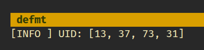
Read RFID Card UID Using USB Serial
Before we begin, make sure to check out the USB serial tutorial for setting up USB serial on the Pico. We will not go over the USB setup again here to keep things simple.
In this section, we will read the UID of an RFID card and print it using USB serial. This approach is useful when you do not have a debug probe and want the Pico to appear as a serial device on your computer.
The RFID logic remains the same as the previous section. The only difference is how we print the UID.
mfrc522 Driver
We will continue using the mfrc522 crate to communicate with the RC522 RFID reader. The driver handles card detection and UID reading. No changes are required on the RFID side.
Project from template
We will start by creating a new project using the template.
cargo generate --git https://github.com/ImplFerris/pico2-template.git --tag v0.3.2
When prompted, enter a project name, for example “uid-over-usb”, and select “Embassy” as the HAL. You do not need to enable defmt for this setup.
Additional Crates required
Update your Cargo.toml and add the following crates along with the existing dependencies:
mfrc522 = "0.8.0"
embedded-hal-bus = "0.3.0"
embassy-usb-logger = "0.5.1"
log = "0.4"
heapless = "0.9.2"
The embassy-usb-logger crate provides logging support over USB. The log crate is used for logging macros such as log::info!. The heapless crate is used to format the UID without heap allocation.
Additional imports
#![allow(unused)]
fn main() {
// For USB
use embassy_rp::{peripherals::USB, usb};
// For SPI
use embassy_rp::spi;
use embassy_rp::spi::Spi;
use embassy_time::Delay;
use embedded_hal_bus::spi::ExclusiveDevice;
// For CS Pin
use embassy_rp::gpio::{Level, Output};
// Driver for the MFRC522
use mfrc522::{Mfrc522, comm::blocking::spi::SpiInterface};
// to prepare buffer with data before writing into USB serial
use core::fmt::Write;
use heapless::String;
}USB Logger Setup
First, we need to bind the USB interrupt handler. This tells Embassy which interrupt handler to use for USB communication:
#![allow(unused)]
fn main() {
embassy_rp::bind_interrupts!(struct Irqs {
USBCTRL_IRQ => usb::InterruptHandler<USB>;
});
}Next, we create an async task that will handle the USB logging. This task runs in the background and manages all USB serial communication:
#![allow(unused)]
fn main() {
#[embassy_executor::task]
async fn logger_task(usb: embassy_rp::Peri<'static, embassy_rp::peripherals::USB>) {
let driver = embassy_rp::usb::Driver::new(usb, Irqs);
embassy_usb_logger::run!(1024, log::LevelFilter::Info, driver);
}
}The #[embassy_executor::task] attribute marks this function as an async task that can be spawned by the Embassy executor. The task accepts the USB peripheral as a parameter and creates a USB driver with our interrupt configuration. The embassy_usb_logger::run! macro sets up the USB logger with a 1024-byte buffer and Info log level filtering.r
Helper Function to Print UID in Hex
We’ll use this helper function to convert the u8 byte array (in this case UID) into a printable hex string. You could also just use raw bytes and enable hex mode in tio (requires latest version) or minicom, but I find this approach easier. In hex mode, it prints everything in hex, including normal text.
#![allow(unused)]
fn main() {
fn print_hex_to_serial(data: &[u8]) {
let mut buff: String<64> = String::new();
for &d in data.iter() {
write!(buff, "{:02x} ", d).expect("failed to write byte into buffer");
}
log::info!("UID: {}", buff);
}
}This function creates a fixed-size string buffer on the stack (no heap allocation required) and formats each byte as a two-digit hexadecimal number. The formatted string is then sent through the logging system.
Spawn the Logger Task
In the main function, we need to spawn the logger task and give it time to initialize:
#![allow(unused)]
fn main() {
spawner.must_spawn(logger_task(p.USB));
Timer::after_secs(3).await;
}The spawner.must_spawn() method starts the logger task inside the Embassy executor. This task runs alongside our main code and handles USB serial logging. We then wait for 3 seconds to give the host computer time to recognize the Pico as a USB serial device and for the logger to be ready. This delay is important because the USB connection is set up gradually, and log messages sent too early may not show up on the host.
Setting Up SPI for the RFID Reader
SPI setup is the same as before.
#![allow(unused)]
fn main() {
let miso = p.PIN_0;
let cs_pin = Output::new(p.PIN_1, Level::High);
let clk = p.PIN_2;
let mosi = p.PIN_3;
let mut config = spi::Config::default();
config.frequency = 1000_000;
let spi_bus = Spi::new_blocking(p.SPI0, clk, mosi, miso, config);
}This configures the SPI bus with a frequency of 1 MHz, which is suitable for the RC522 module. The chip select (CS) pin is initialized high (inactive state), as SPI chip select is active low.
Getting the SpiDevice from SPI Bus
The mfrc522 driver expects an SpiDevice rather than a raw SPI bus. We use the embedded-hal-bus crate to create this device:
#![allow(unused)]
fn main() {
let spi = ExclusiveDevice::new(spi_bus, cs_pin, Delay).expect("Failed to get exclusive device");
}We use ExclusiveDevice since our setup has just one device on the SPI bus. This wrapper holds the SPI bus and CS pin together, automatically controlling the chip select line during each read or write operation. The delay parameter provides timing control between operations.
Initialize the mfrc522
With the SPI device ready, we can now initialize the RFID reader.
#![allow(unused)]
fn main() {
let itf = SpiInterface::new(spi);
log::info!("Initializing MFRC522...");
let mut rfid = match Mfrc522::new(itf).init() {
Ok(rfid) => {
log::info!("MFRC522 initialized successfully");
rfid
}
Err(e) => {
log::error!("Failed to initialize MFRC522: {:?}", e);
loop {
Timer::after_secs(1).await;
}
}
};
}The SpiInterface wraps our SPI device for use with the mfrc522 driver. We then attempt to initialize the RFID reader. If initialization succeeds, we log a success message and continue. If it fails, we log the error and enter an infinite loop, as we cannot proceed without a working RFID reader.
Read the UID and Print
The main loop continuously checks for nearby RFID cards. When a card is detected, we read its UID and display it:
#![allow(unused)]
fn main() {
log::info!("Waiting for RFID");
loop {
if let Ok(atqa) = rfid.reqa() {
if let Ok(uid) = rfid.select(&atqa) {
print_hex_to_serial(uid.as_bytes());
Timer::after_millis(500).await;
}
}
Timer::after_millis(100).await;
}
}The reqa method sends a Request command to detect cards in proximity. When a card responds with its ATQA (Answer To Request), we call select to perform the anti-collision protocol and retrieve the UID. The UID bytes are formatted as hexadecimal and sent through the log system to the USB serial console.
The 500ms delay after a successful read prevents flooding the serial output with repeated reads of the same card. The 100ms delay in the main loop provides a reasonable polling interval without consuming excessive CPU cycles.
Clone the existing project
You can clone (or refer) project I created and navigate to the uid-over-usb folder.
git clone https://github.com/ImplFerris/pico2-embassy-projects
cd pico2-embassy-projects/rfid/uid-over-usb/
How to Run ?
The method to flash (run the code) on the Pico is the same as usual. However, we need to set up tio to interact with the Pico through the serial port (/dev/ttyACM0). This allows us to read data from the Pico or send data to it.
tio
Make sure you have tio installed on your system. If not, you can install it using:
apt install tio
Connecting to the Serial Port
Run the following command to connect to the Pico’s serial port:
tio /dev/ttyACM0
This will open a terminal session for communicating with the Pico. The /dev/ttyACM0 device appears when the Pico is recognized by the host as a USB CDC ACM device.
Flashing and Running the Code
Open another terminal, navigate to the project folder, and flash the code onto the Pico as usual:
cargo run --release
If everything is set up correctly, you should see a “Connected” message in the tio terminal.
Reading the UID
Now, bring the RFID tag near the reader. You should see the UID bytes displayed in hex format on the USB serial terminal. Each byte is shown as a two-digit hexadecimal number.
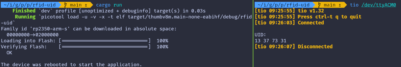
rp-hal version
If you are interested in an rp-hal based version of this example, you can find it in the repository below. Clone the repository and navigate to the print-uid project:
git clone https://github.com/ImplFerris/pico2-rp-projects
cd pico2-rp-projects/rfid/print-uid/
Turn on LED When RFID UID Matches
In this section, we’ll use the UID obtained in the previous chapter and hardcode it into our program. The LED will turn on only when the matching RFID tag is nearby; otherwise, it will remain off. When you bring the RFID tag close, the LED will light up. If you bring a different tag, like a key fob or any other RFID tag, the LED will turn off.
This should give you a basic authorized vs unauthorized feel. Simply checking the UID is not enough for real security, and we will go deeper into reading and authentication in the next chapter. For now, this is a simple and fun way to get started. You can also extend this example by adding an OLED display and showing Authorized or Unauthorized messages instead of using an LED.
Getting Your Card’s UID
Before writing the LED control logic, you need to know the UID of your RFID card.
Run the code from the previous chapter that prints the UID. When you bring your card near the reader, you will see output like this:
UID: 13 37 73 31
These are the four bytes you’ll hardcode into the program as [0x13, 0x37, 0x73, 0x31].
Logic
The logic used here is straightforward. The LED is kept off by default. The program continuously checks for an RFID tag. When a tag is detected, its UID is read and compared with the hardcoded UID. If they match, the LED is turned on. If they do not match, or if no tag is present, the LED remains off.
#![allow(unused)]
fn main() {
// Replace the UID Bytes with your tag UID
const TAG_UID: [u8; 4] = [0x13, 0x37, 0x73, 0x31];
let mut led = Output::new(p.PIN_25, Level::Low);
loop {
led.set_low();
if let Ok(atqa) = rfid.reqa() {
if let Ok(uid) = rfid.select(&atqa) {
if *uid.as_bytes() == TAG_UID {
led.set_high();
Timer::after_millis(500).await;
}
}
}
Timer::after_millis(100).await;
}
}Clone the existing project
You can clone (or refer) project I created and navigate to the rfid-led folder.
git clone https://github.com/ImplFerris/pico2-embassy-projects
cd pico2-embassy-projects/rfid/rfid-led/
Light it Up
Flash the program onto the Pico as you normally would:
# if you are using debug probe
# cargo flash --release
cargo embed --release
# if you are using BOOTSEL approach
cargo run --release
Once the program is running, bring the matching RFID tag near the reader and observe the onboard LED turning on. Move the tag away and the LED turns off. Try a different card or key fob and you will see that the LED does not turn on for non matching UIDs.
rp-hal version
If you are interested in an rp-hal based version of this example, you can find it in the repository below. Clone the repository and navigate to the rfid-led project:
git clone https://github.com/ImplFerris/pico2-rp-projects
cd pico2-rp-projects/rfid/rfid-led/
Reading RFID Tag Data on Raspberry Pi Pico with Embedded Rust
In this chapter, we move beyond just reading the UID and start reading actual data stored on the RFID tag. We will read all the blocks from the first sector, which is sector 0.
As mentioned earlier, reading or writing data on an RFID tag is not possible directly. Before accessing a block, we must first authenticate with the sector that contains that block. Once authentication succeeds, the reader is allowed to read or write the blocks in that sector.
Select Your Output Method
In this chapter, the instructions and code differ slightly depending on how you are printing the output. Select the appropriate tab based on whether you are using a debug probe or USB serial.
In this setup, we use defmt over RTT to print the block data.
Project from Template
We will start by creating a new project using the template.
cargo generate --git https://github.com/ImplFerris/pico2-template.git --tag v0.3.2
When prompted, enter a project name, for example “read-blocks”, and select “Embassy” as the HAL. Ensure to enable “defmt” for logging.
Additional Crates Required
Update your Cargo.toml to add the required crates along with the existing dependencies.
mfrc522 = "0.8.0"
embedded-hal-bus = "0.3.0"
heapless = { version = "0.9.2", features = ["defmt"] }
Additional Imports
#![allow(unused)]
fn main() {
// For SPI
use embassy_rp::spi::Spi;
use embassy_rp::{self as hal, spi};
use embassy_time::Delay;
use embedded_hal_bus::spi::ExclusiveDevice;
// For CS Pin
use embassy_rp::gpio::{Level, Output};
// Driver for the MFRC522
use mfrc522::{Mfrc522, comm::blocking::spi::SpiInterface};
// to prepare buffer with data before logging
use core::fmt::Write;
use heapless::String;
}Reusing the existing setup
The remaining SPI and RFID reader initialization is the same as in the previous chapter. You can reuse that setup here without any changes. In this chapter, we only add a few helper functions and modify the main loop to read blocks and print their contents.
Authentication
Most MIFARE Classic tags ship with a default sector key. The most common default key is six bytes of 0xFF. If authentication fails, you may need to check the tag documentation or try a different key.
For authentication, we need three things:
- The tag UID, which we already obtain using the REQA and select steps
- The absolute block number we want to authenticate against
- The key used for authentication, which is hardcoded in this example
Helper function to print bytes as hex dump
This helper converts raw bytes into a hexadecimal format and prints them.
#![allow(unused)]
fn main() {
fn print_hex(data: &[u8]) {
let mut buff: String<64> = String::new();
for &d in data.iter() {
write!(buff, "{:02x} ", d).expect("failed to write byte into buffer");
}
defmt::println!("{}", buff);
}
}Read the block
Once authentication with a sector succeeds, the RFID reader is allowed to access the blocks that belong to that sector. From this point on, the reader can issue read commands for those blocks.
Each block on a MIFARE Classic tag stores exactly 16 bytes of data. The mf_read function provided by the mfrc522 crate reads one block at a time and returns these 16 bytes when the operation succeeds. If the read fails, an error is returned.
In this chapter, we focus on sector 0. Sector 0 contains four blocks. Authentication is performed once for the sector, and all four blocks are read in sequence. As long as we stay within the same sector, authentication does not need to be repeated.
#![allow(unused)]
fn main() {
fn read_sector<E, COMM>(
uid: &mfrc522::Uid,
sector: u8,
rfid: &mut Mfrc522<COMM, mfrc522::Initialized>,
) -> Result<(), &'static str>
where
COMM: mfrc522::comm::Interface<Error = E>,
{
const AUTH_KEY: [u8; 6] = [0xFF; 6];
let block_offset = sector * 4;
rfid.mf_authenticate(uid, block_offset, &AUTH_KEY)
.map_err(|_| "Auth failed")?;
for abs_block in block_offset..block_offset + 4 {
let data = rfid.mf_read(abs_block).map_err(|_| "Read failed")?;
print_hex(&data);
}
Ok(())
}
}When accessing memory on the tag, we have to refer to blocks using absolute block numbers. The tag treats all blocks as part of one continuous sequence rather than using sector local numbering. For example, sector 0 uses blocks 0 to 3, sector 1 uses blocks 4 to 7, and sector 2 uses blocks 8 to 11.
To convert a sector number into the correct block number, we calculate an offset. Since each sector contains four blocks, multiplying the sector number by 4 gives the first block of that sector. This value is stored in block_offset and is then used as the starting point to read all blocks that belong to the selected sector.
For the first sector, which is sector 0, the calculation is straightforward. The offset is 0 * 4, which gives block 0. This means sector 0 starts at block 0 and includes blocks 0, 1, 2, and 3. These are the blocks we read when we authenticate and access the first sector.
The main loop
The main loop operates similarly to what we covered in the previous chapter. After selecting a tag, we proceed to read its blocks. Once the block data is read, the loop sends the HLTA and stop_crypto1 commands to put the card in HALT state.
#![allow(unused)]
fn main() {
loop {
if let Ok(atqa) = rfid.reqa() {
if let Ok(uid) = rfid.select(&atqa) {
if let Err(e) = read_sector(&uid, 0, &mut rfid) {
defmt::error!("Error reading sector: {:?}", e);
}
let _ = rfid.hlta();
let _ = rfid.stop_crypto1();
Timer::after_millis(100).await;
}
}
Timer::after_millis(100).await;
}
}Clone the existing project
You can clone (or refer) project I created and navigate to the read-blocks folder.
git clone https://github.com/ImplFerris/pico2-embassy-projects
cd pico2-embassy-projects/rfid/read-blocks/
How to Run?
Use cargo embed to flash and run the program, since the template already configures RTT and defmt and the output appears in the terminal after flashing completes.
cargo embed --release
Reading the Block Data
Bring the RFID tag close to the reader, and the system console will display the data bytes read from all blocks in the first sector (sector 0).
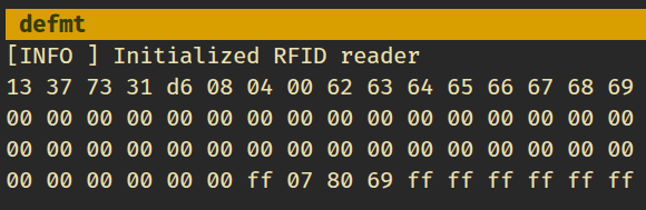
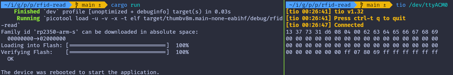
rp-hal version
If you are interested in an rp-hal based version of this example, you can find it in the repository below. Clone the repository and navigate to the read-blocks project:
git clone https://github.com/ImplFerris/pico2-rp-projects
cd pico2-rp-projects//rfid/read-blocks/
Dump Entire Memory
So far, you have learned how to authenticate a sector and read the blocks inside it. In the previous chapter, we limited ourselves to sector 0. In this chapter, we extend that approach to dump the entire memory of the tag.
We will loop through all sectors on the tag, authenticate each sector, and read every block inside it. Since authentication is valid only for a single sector, we must authenticate again whenever we move to the next sector.
For each sector, we will read all four blocks and print their 16 byte contents. To make the output easier to understand, we will add labels that show:
- The sector number
- The absolute block number
- The block number relative to the sector
- Whether the block is manufacturer data, a sector trailer, or normal data
To keep this chapter focused, we will not repeat the project creation or dependency setup steps. By now, you should already be comfortable with the required crates and project structure.
Select Your Output Method
As before, the core logic is the same for both setups. Only the logging output differs slightly.
Select the tab that matches how you are printing the output.
In this setup, we use defmt over RTT to print the block data.
Loop through the sector
We start by creating a helper function that iterates through all sectors on the tag. For a MIFARE Classic 1K tag, this means sectors 0 through 15.
For each sector, we print a header and then call read_sector to authenticate and read its blocks.
#![allow(unused)]
fn main() {
fn dump_memory<E, COMM>(
uid: &mfrc522::Uid,
rfid: &mut Mfrc522<COMM, mfrc522::Initialized>,
) -> Result<(), &'static str>
where
COMM: mfrc522::comm::Interface<Error = E>,
{
let mut buff: String<64> = String::new();
for sector in 0..16 {
// Printing the Sector number
write!(buff, "-----------SECTOR {}-----------", sector)
.expect("failed to write into heapless buff");
defmt::println!("{}", buff);
buff.clear();
read_sector(uid, sector, rfid)?;
}
Ok(())
}
}Identify Block Type
Next, we add a small helper function that determines the type of a block based on its position within a sector.
#![allow(unused)]
fn main() {
fn get_block_type(sector: u8, rel_block: u8) -> &'static str {
match rel_block {
0 if sector == 0 => "MFD",
3 => "TRAILER",
_ => "DATA",
}
}
}Reading a Sector with Labels
The read_sector function is similar to what you used earlier, but now it adds more context to the output.
#![allow(unused)]
fn main() {
fn read_sector<E, COMM>(
uid: &mfrc522::Uid,
sector: u8,
rfid: &mut Mfrc522<COMM, mfrc522::Initialized>,
) -> Result<(), &'static str>
where
COMM: mfrc522::comm::Interface<Error = E>,
{
const AUTH_KEY: [u8; 6] = [0xFF; 6];
let mut buff: String<64> = String::new();
let block_offset = sector * 4;
rfid.mf_authenticate(uid, block_offset, &AUTH_KEY)
.map_err(|_| "Auth failed")?;
for abs_block in block_offset..block_offset + 4 {
let rel_block = abs_block - block_offset;
let data = rfid.mf_read(abs_block).map_err(|_| "Read failed")?;
// Printing the block data
for &d in data.iter() {
write!(buff, "{:02x} ", d).expect("failed to write byte into buffer");
}
// Printing block type
let block_type = get_block_type(sector, rel_block);
defmt::println!(
"BLOCK {} (REL: {}) | {} | {}",
abs_block,
rel_block,
buff,
block_type
);
buff.clear();
}
defmt::println!("");
Ok(())
}
}The main loop
The main loop stays mostly the same. The only difference is that we now call dump_memory instead of reading a single sector.
#![allow(unused)]
fn main() {
loop {
if let Ok(atqa) = rfid.reqa() {
if let Ok(uid) = rfid.select(&atqa) {
if let Err(e) = dump_memory(&uid, &mut rfid) {
defmt::error!("Error reading sector: {:?}", e);
}
let _ = rfid.hlta();
let _ = rfid.stop_crypto1();
Timer::after_millis(500).await;
}
}
Timer::after_millis(200).await;
}
}Clone the existing project
You can clone (or refer) project I created and navigate to the memory-dump folder.
git clone https://github.com/ImplFerris/pico2-embassy-projects
cd pico2-embassy-projects/rfid/memory-dump/
Dump
When you run the program and bring your tag or key fob close, you should see output like this. If you notice the 0x40..0x43 bytes in the block 18 (the block 2 of the sector 4) and wonder why it’s there; good catch! That’s the custom data I wrote to the tag.
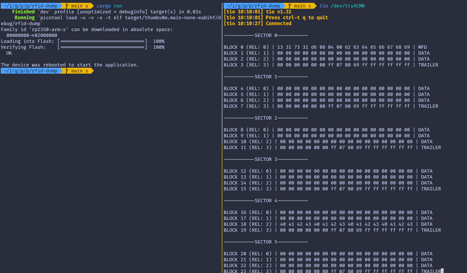
Write Data
In the previous chapters, we focused on reading data from the tag. In this chapter, we move one step further and write data to the tag memory.
We will write data to block 2 of sector 4. To clearly see the effect of the write operation, we first read and print the block contents before writing, then read the same sector again after the write completes.
Writing is done using the mf_write function provided by the mfrc522 crate. This function writes exactly 16 bytes, which matches the size of a single block on a MIFARE Classic tag.
Caution
Writing to the wrong block can permanently change authentication keys or access bits. Avoid writing to sector trailer blocks unless you fully understand their structure.
Writing a Block
We begin by defining a helper function that performs the write operation. The function receives the tag UID, the sector number, the block number relative to the sector, a 16 byte data buffer, and a mutable reference to the RFID reader. Inside the function, the absolute block number is calculated and the sector is authenticated before the write is performed.
#![allow(unused)]
fn main() {
fn write_block<E, COMM>(
uid: &mfrc522::Uid,
sector: u8,
rel_block: u8,
data: [u8; 16],
rfid: &mut Mfrc522<COMM, mfrc522::Initialized>,
) -> Result<(), &'static str>
where
COMM: mfrc522::comm::Interface<Error = E>,
{
const AUTH_KEY: [u8; 6] = [0xFF; 6];
let block_offset = sector * 4;
let abs_block = block_offset + rel_block;
rfid.mf_authenticate(uid, block_offset, &AUTH_KEY)
.map_err(|_| "Auth failed")?;
rfid.mf_write(abs_block, data).map_err(|_| "Write failed")?;
Ok(())
}
}Preparing the Data
Each block stores exactly 16 bytes. When writing text or smaller values, the remaining bytes still need to be provided. In this example, we write the string implRust and pad the remaining bytes with 0x00.
#![allow(unused)]
fn main() {
let target_sector = 4;
let rel_block = 2;
const DATA: [u8; 16] = [
b'i', b'm', b'p', b'l', b'R', b'u', b's', b't', // "implRust"
0x00, 0x00, 0x00, 0x00, 0x00, 0x00, 0x00, 0x00, // Remaining bytes as 0x00
];
}Main Loop
The main loop follows a simple sequence. After detecting and selecting a tag, the current contents of the target sector are read and printed. The new data is then written to the selected block, and the sector is read again to confirm the change. Finally, the tag is placed into the HALT state and encryption is stopped.
If you are using USB serial instead of a debug probe, replace defmt::info! and defmt::error! with log::info! and log::error!.
#![allow(unused)]
fn main() {
loop {
if let Ok(atqa) = rfid.reqa() {
if let Ok(uid) = rfid.select(&atqa) {
defmt::info!("\r\n----Before Write----\r\n");
if let Err(e) = read_sector(&uid, target_sector, &mut rfid) {
defmt::error!("Error reading sector: {:?}", e);
}
if let Err(e) = write_block(&uid, target_sector, rel_block, DATA, &mut rfid) {
defmt::error!("Error writing data: {:?}", e);
}
defmt::info!("\r\n----After Write----\r\n");
if let Err(e) = read_sector(&uid, target_sector, &mut rfid) {
defmt::error!("Error reading sector: {:?}", e);
}
let _ = rfid.hlta();
let _ = rfid.stop_crypto1();
Timer::after_millis(500).await;
}
}
Timer::after_millis(100).await;
}
}Clone the existing project
You can clone the example project and navigate to the write example directory.
git clone https://github.com/ImplFerris/pico2-embassy-projects
cd pico2-embassy-projects/rfid/write-data/
Output
When the program runs successfully, the output shows the block contents before and after the write. You should see the ASCII bytes for implRust appear in block 2, confirming that the write operation worked as expected.
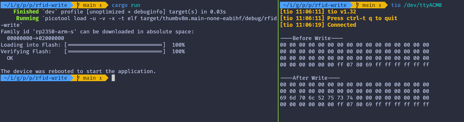
rp-hal version
If you are interested in an rp-hal based version of this example, you can find it in the repository below. Clone the repository and navigate to the write-data project:
git clone https://github.com/ImplFerris/pico2-rp-projects
cd pico2-rp-projects/rfid/write-data/
Changing the Authentication Key
In this chapter, we change the authentication key for a sector. Specifically, we update Key A of sector 1. By default, both Key A and Key B on a MIFARE Classic 1K card are set to FF FF FF FF FF FF. We will replace Key A with the value 52 75 73 74 65 64, which is the hex representation of the ASCII string “Rusted”.
To change the key, we must write to the sector trailer, which is block 3 of the sector. The rest of the sector data must remain untouched. Writing to the trailer block is a sensitive operation, so it is important to be careful.
Before making any changes, it is strongly recommended to inspect the current contents of the sector trailer. You can do this by running the Dump Memory or Read Data program from the earlier chapters.
Note
Default Keys: On a MIFARE Classic 1K card, both Key A and Key B are initially set to FF FF FF FF FF FF. When reading a trailer block, Key A is not returned and appears as 00 00 00 00 00 00, while Key B is returned as stored.
In this example, we also update Key B so that it is easy to confirm that the write operation succeeded. Key B is set to the hex bytes for the ASCII string “Ferris”, which is 46 65 72 72 69 73.
The program prints the contents of the sector before and after writing. After the key is changed, attempting to authenticate again with the old key will fail. This is expected behavior and confirms that the new key is now active.
Key and Trailer Data
The data written to the trailer block contains three parts. The first six bytes are the new Key A value, followed by the access bits and trailer byte, and finally the six bytes for Key B.
The current authentication key is set to the default value. The new key is extracted from the first six bytes of the data array so that it can be reused when reading the sector after the update.
#![allow(unused)]
fn main() {
let target_sector = 1;
let rel_block = 3;
const DATA: [u8; 16] = [
0x52, 0x75, 0x73, 0x74, 0x65, 0x64, // Key A: "Rusted"
0xFF, 0x07, 0x80, 0x69, // Access bits and trailer byte
0x46, 0x65, 0x72, 0x72, 0x69, 0x73, // Key B: "Ferris"
];
let current_key = &[0xFF, 0xFF, 0xFF, 0xFF, 0xFF, 0xFF];
let new_key: &[u8; 6] = &DATA[..6].try_into().expect("have enough data");
}Writing the Trailer Block
The write function is slightly modified to accept the authentication key as an argument. This allows us to authenticate with the old key before writing and then authenticate with the new key afterward.
#![allow(unused)]
fn main() {
fn write_block<E, COMM>(
uid: &mfrc522::Uid,
sector: u8,
rel_block: u8,
data: [u8; 16],
key: &[u8; 6],
rfid: &mut Mfrc522<COMM, mfrc522::Initialized>,
) -> Result<(), &'static str>
where
COMM: mfrc522::comm::Interface<Error = E>,
{
let block_offset = sector * 4;
let abs_block = block_offset + rel_block;
rfid.mf_authenticate(uid, block_offset, key)
.map_err(|_| "Auth failed")?;
rfid.mf_write(abs_block, data).map_err(|_| "Write failed")?;
Ok(())
}
}Reading a Sector with a Custom Key
The read function is updated in the same way. It now accepts the key as an argument and uses it during authentication.
#![allow(unused)]
fn main() {
fn read_sector<E, COMM>(
uid: &mfrc522::Uid,
sector: u8,
key: &[u8; 6],
rfid: &mut Mfrc522<COMM, mfrc522::Initialized>,
) -> Result<(), &'static str>
where
COMM: mfrc522::comm::Interface<Error = E>,
{
let block_offset = sector * 4;
rfid.mf_authenticate(uid, block_offset, key)
.map_err(|_| "Auth failed")?;
for abs_block in block_offset..block_offset + 4 {
let data = rfid.mf_read(abs_block).map_err(|_| "Read failed")?;
print_hex(&data);
}
Ok(())
}
}The main loop
The main loop follows the same structure as earlier chapters. First, the sector is read using the current key. Then the trailer block is written with the new key. Finally, the sector is read again using the new key to confirm the change.
If you are using USB serial instead of a debug probe, replace defmt::println! and defmt::error! with log::info! and log::error!.
#![allow(unused)]
fn main() {
loop {
if let Ok(atqa) = rfid.reqa() {
if let Ok(uid) = rfid.select(&atqa) {
defmt::println!("\r\n----Before Write----\r\n");
if let Err(e) = read_sector(&uid, target_sector, current_key, &mut rfid) {
defmt::error!("Error reading sector: {:?}", e);
}
Timer::after_millis(200).await;
if let Err(e) =
write_block(&uid, target_sector, rel_block, DATA, current_key, &mut rfid)
{
defmt::error!("Error writing block: {:?}", e);
}
Timer::after_millis(200).await;
defmt::println!("\r\n----After Write----\r\n");
if let Err(e) = read_sector(&uid, target_sector, new_key, &mut rfid) {
defmt::error!("Error reading sector: {:?}", e);
}
let _ = rfid.hlta();
let _ = rfid.stop_crypto1();
Timer::after_millis(500).await;
}
}
Timer::after_millis(200).await;
}
}Clone the existing project
You can clone (or refer) project I created and navigate to the change-key folder.
git clone https://github.com/ImplFerris/pico2-embassy-projects
cd pico2-embassy-projects/change-key/
Output
When the program runs, the sector contents are printed before and after the write. After the key is changed, bringing the tag back to the reader will result in an authentication failure when using the old key. This confirms that the new key 52 75 73 74 65 64 (Rusted) is now active.
Note
After the key update, if you bring the tag close to the reader again, authentication will fail because the program will be still using the old hardcoded current_key.
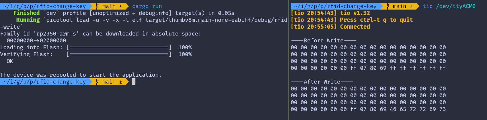
You can further verify this by updating the read-data program to use the new key and running it again.
Access Control
The tag includes access bits that enable access control for the data stored in the tag. This chapter will explore how these access bits function. This section might feel a bit overwhelming, so I’ll try to make it as simple and easy to understand as possible.
Caution
Modifying Access Bits: Be careful when writing the access bits, as incorrect values can make the sector unusable.
Permissions
These are the fundamental permissions that will be used to define access conditions. The table explains each permission operation and specifies the blocks to which it is applicable: normal data blocks (read/write), value blocks, or sector trailers.
| Operation | Description | Applicable for Block Type |
|---|---|---|
| Read | Reads one memory block | Read/Write, Value, Sector Trailer |
| Write | Writes one memory block | Read/Write, Value, Sector Trailer |
| Increment | Increments the contents of a block and stores the result in the internal Transfer Buffer | Value |
| Decrement | Decrements the contents of a block and stores the result in the internal Transfer Buffer | Value |
| Restore | Reads the contents of a block into the internal Transfer Buffer | Value |
| Transfer | Writes the contents of the internal Transfer Buffer to a block | Value, Read/Write |
Access conditions
Let’s address the elephant in the room: The access conditions. During my research, I found that many people struggled to make sense of the access condition section in the datasheet. Here is my attempt to explain it for easy to understand 🤞.
You can use just 3 bit-combinations per block to control its permissions. In the official datasheet, this is represented using a notation like CXY (C1₀, C1₂… C3₃) for the access bits. The first number (X) in this notation refers to the access bit number, which ranges from 1 to 3, each corresponding to a specific permission type. However, the meaning of these permissions varies depending on whether the block is a data block or a trailer block. The second number (Y) in the subscript denotes the relative block number, which ranges from 0 to 3.
Table 1: Access conditions for the sector trailer
In the original datasheet, the subscript number is not specified in the table. I have added the subscript “3”, as the sector trailer is located at Block 3.
Important
Readable Key: If you can read the key, it cannot be used as an authentication key. Therefore, in this table, whenever Key B is readable, it cannot serve as the authentication key. If you’ve noticed, yes, the Key A can never be read.
| Access Bits | Access Condition for | Remark | |||||||
|---|---|---|---|---|---|---|---|---|---|
| Key A | Access Bits | Key B | |||||||
| C13 | C23 | C33 | Read | Write | Read | Write | Read | Write | |
| 0 | 0 | 0 | never | key A | key A | never | key A | key A | Key B may be read |
| 0 | 1 | 0 | never | never | key A | never | key A | never | Key B may be read |
| 1 | 0 | 0 | never | key B | key A|B | never | never | key B | |
| 1 | 1 | 0 | never | never | key A|B | never | never | never | |
| 0 | 0 | 1 | never | key A | key A | key A | key A | key A | Key B may be read; Default configuration |
| 0 | 1 | 1 | never | key B | key A|B | key B | never | key B | |
| 1 | 0 | 1 | never | never | key A|B | key B | never | never | |
| 1 | 1 | 1 | never | never | key A|B | never | never | never | |
How to make sense out of this table?
It is a simple table showing the correlation between bit combinations and permissions.
For example: Let’s say you select “1 0 0” (3rd row in the table), then you can’t read KeyA, KeyB. However, you can modify the KeyA as well as KeyB value with KeyB. You can Read Access Bits with either KeyA or KeyB. But, you can never modify the Access Bits.
Now, where should these bits be stored? We will place them in the 6th, 7th, and 8th bytes at a specific location, which will be explained shortly.
Table 2: Access conditions for data blocks
This applies to all data blocks. The original datasheet does not include the subscript “Y”, I have added it for context. Here, “Y” represents the block number (ranging from 0 to 2).
The default config here indicates that both Key A and Key B can perform all operations. However, as seen in the previous table, Key B is readable (in default config), making it unusable for authentication. Therefore, only Key A can be used.
| Access Bits | Access Condition for | Application | |||||
|---|---|---|---|---|---|---|---|
| C1Y | C2Y | C3Y | Read | Write | Increment | Decrement,Transfer/Restore | |
| 0 | 0 | 0 | key A|B | key A|B | key A|B | key A|B | Default configuration |
| 0 | 1 | 0 | key A|B | never | never | never | read/write block |
| 1 | 0 | 0 | key A|B | key B | never | never | read/write block |
| 1 | 1 | 0 | key A|B | key B | key B | key A|B | value block |
| 0 | 0 | 1 | key A|B | never | never | key A|B | value block |
| 0 | 1 | 1 | key B | key B | never | never | read/write block |
| 1 | 0 | 1 | key B | never | never | never | read/write block |
| 1 | 1 | 1 | never | never | never | never | read/write block |
How to make sense out of this table?
It’s similar to the previous one; it shows the relationship between bit combinations and permissions.
For example: If you select “0 1 0” (2nd row in the table) and use this permission for block 1, you can use either KeyA or KeyB to read block 1. However, no other operations can be performed on block 1.
The notation for this is as follows: the block number is written as a subscript to the bit labels (e.g., C11, C21, C31). Here, the subscript “1” represents block 1. For the selected combination “0 1 0”, this means:
- C11 = 0
- C21 = 1
- C31 = 0
These bits will also be placed in the 6th, 7th, and 8th bytes at a specific location, which will be explained shortly.
Table 3: Access conditions table
Let’s colorize the original table to better visualize what each bit represents. The 7th and 3rd bits in each byte are related to the sector trailer. The 6th and 2nd bits correspond to Block 2. The 5th and 1st bits are associated with Block 1. The 4th and 0th bits are related to Block 0.
The overline on the notation indicates inverted values. This means that if the CXy value is 0, then CXy becomes 1.
| Byte | 7 | 6 | 5 | 4 | 3 | 2 | 1 | 0 |
|---|---|---|---|---|---|---|---|---|
| Byte 6 | C23 | C22 | C21 | C20 | C13 | C12 | C11 | C10 |
| Byte 7 | C13 | C12 | C11 | C10 | C33 | C32 | C31 | C30 |
| Byte 8 | C33 | C32 | C31 | C30 | C23 | C22 | C21 | C20 |
The default access bit “FF 07 80”. Let’s try to understand what it means.
| Byte | 7 | 6 | 5 | 4 | 3 | 2 | 1 | 0 |
|---|---|---|---|---|---|---|---|---|
| Byte 6 | 1 | 1 | 1 | 1 | 1 | 1 | 1 | 1 |
| Byte 7 | 0 | 0 | 0 | 0 | 0 | 1 | 1 | 1 |
| Byte 8 | 1 | 0 | 0 | 0 | 0 | 0 | 0 | 0 |
We can derive the CXY values from the table above. Notice that only C33 is set to 1, while all other values are 0. Now, refer to Table 1 and Table 2 to understand which permission this corresponds to.
| Block | C1Y | C2Y | C3Y | Access |
|---|---|---|---|---|
| Block 0 | 0 | 0 | 0 | All permissions with Key A |
| Block 1 | 0 | 0 | 0 | All permissions with Key A |
| Block 2 | 0 | 0 | 0 | All permissions with Key A |
| Block 3 (Trailer) | 0 | 0 | 1 | You can write Key A using Key A. Access Bits and Key B can only be read and written using Key A. |
Since Key B is readable, you cannot use it for authentication.
Calculator on next page
Still confused? Use the calculator on the next page to experiment with different combinations. Adjust the permissions for each block and observe how the Access Bits values change accordingly.
Reference
MIFARE Classic 1K Access Bits Calculator
Decode: You can modify the “Access bits” and the Data Block and Sector Trailer tables will automatically update.
Encode: Click the “Edit” button in each row of the table to select your preferred access conditions. This will update the Access Bits.
Caution
Writing an incorrect value to the access condition bits can make the sector inaccessible.
Access Bits
Data Block Access Conditions:
| Block | C1Y | C2Y | C3Y | Read | Write | Increment | Decrement/Transfer/Restore | Remarks | Action |
|---|---|---|---|---|---|---|---|---|---|
| Block 0 | 0 | 0 | 0 | key A|B | key A|B | key A|B | key A|B | Default configuration | |
| Block 1 | 0 | 0 | 0 | key A|B | key A|B | key A|B | key A|B | Default configuration | |
| Block 2 | 0 | 0 | 0 | key A|B | key A|B | key A|B | key A|B | Default configuration |
| C1Y | C2Y | C3Y | Read | Write | Increment | Decrement/Transfer/Restore | Remarks |
|---|---|---|---|---|---|---|---|
| 0 | 0 | 0 | key A|B | key A|B | key A|B | key A|B | Default configuration |
| 0 | 1 | 0 | key A|B | never | never | never | read/write block |
| 1 | 0 | 0 | key A|B | key B | never | never | read/write block |
| 1 | 1 | 0 | key A|B | key B | key B | key A|B | value block |
| 0 | 0 | 1 | key A|B | never | never | key A|B | value block |
| 0 | 1 | 1 | key B | key B | never | never | read/write block |
| 1 | 0 | 1 | key B | never | never | never | read/write block |
| 1 | 1 | 1 | never | never | never | never | read/write block |
Sector Trailer (Block 3) Access Conditions:
| C13 | C23 | C33 | Read Key A | Write Key A | Read Access Bits | Write Access Bits | Read Key B | Write Key B | Remarks | Action |
|---|---|---|---|---|---|---|---|---|---|---|
| 0 | 0 | 1 | never | key A | key A | key A | key A | key A | Key B may be read; Default configuration |
| C13 | C23 | C33 | Read Key A | Write Key A | Read Access Bits | Write Access Bits | Read Key B | Write Key B | Remarks |
|---|---|---|---|---|---|---|---|---|---|
| 0 | 0 | 0 | never | key A | key A | never | key A | key A | Key B may be read |
| 0 | 1 | 0 | never | never | key A | never | key A | never | Key B may be read |
| 1 | 0 | 0 | never | key B | key A|B | never | never | key B | |
| 1 | 1 | 0 | never | never | key A|B | never | never | never | |
| 0 | 0 | 1 | never | key A | key A | key A | key A | key A | Key B may be read; Default configuration |
| 0 | 1 | 1 | never | key B | key A|B | key B | never | key B | |
| 1 | 0 | 1 | never | never | key A|B | key B | never | never | |
| 1 | 1 | 1 | never | never | key A|B | never | never | never |
References
- This UI is inspired from this calculator: Mifarecalc
- MIFARE-Classic-1K-Access-Bits-Calculator
SD Card (SDC/MMC)
Sooner or later, you may want to store data that does not fit in flash memory. This could be sensor logs, configuration files, game assets, or anything else that needs to survive a power cycle. One of the most practical ways to do this is by using an SD card. In this section, we are going to learn how to use an SD card module with the Raspberry Pi Pico.
MMC (MultiMediaCard)
The MultiMediaCard (MMC) was introduced as an early type of flash memory storage, preceding the SD Card. It was commonly used in devices such as camcorders, digital cameras, and portable music players.
Like modern flash storage, MMC stores data as electrical charge in flash memory cells. This is very different from optical media such as CDs or DVDs, which store data as physical marks read by a laser.
Although MMC cards themselves are mostly obsolete today, they are still relevant because SD cards inherited many ideas from MMC.
SD (Secure Digital) Card
The Secure Digital Card, usually called an SD card, built on the ideas of MMC and expanded them. SD cards became extremely popular and are now used in cameras, embedded systems, and single board computers. There is a smaller variant called the microSD card that is typically used in microcontroller projects.
Image credit: Based on SD card by Tkgd2007, licensed under the GFDL and CC BY-SA 3.0, 2.5, 2.0, 1.0.
Internally, SD cards read and write data in fixed size blocks, typically 512 bytes; Because of this, data is accessed in blocks rather than as individual bytes. Filesystems such as FAT sit on top of these blocks and manage how files are stored and retrieved.
Hardware Requirements
We’ll be using the Micro SD Card adapter module. You can search for either “Micro SD Card Reader Module” or “Micro SD Card Adapter” to find them.
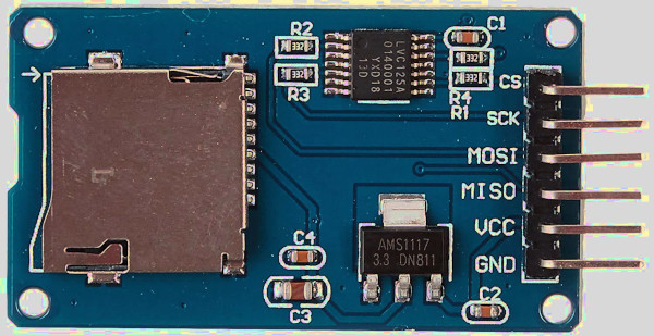
And of course, you’ll need a microSD card. The SD card should be formatted with FAT32; Depending on your computer, you may need a separate SD or USB adapter to format the card, since not all laptops have a microSD slot.
References:
- I highly recommend watching Jonathan Pallant’s talk at Euro Rust 2024 on writing an SD card driver in Rust. He wrote the driver we are going to use (originally he created it to run MS-DOS on ARM). It is not intended for production systems.
- If you want to understand how it works under the hood in SPI mode, you can refer to this article: How to Use MMC/SDC
Connecting Micro SD Card Reader with Raspberry Pi Pico
In this section, we are going to wire a microSD card reader module to the Raspberry Pi Pico using SPI mode.
microSD Card Pin Mapping for SPI Mode
We will focus only on the microSD card itself, since that is what we are using. A microSD card has 8 physical pins, but in SPI mode only 6 of them are actually required.
You may have noticed that most microSD card reader modules also expose only 6 pins. That is because those modules are already wired internally for SPI operation, and the unused pins are simply not brought out.
The table below shows how the microSD card pins map to SPI signals.
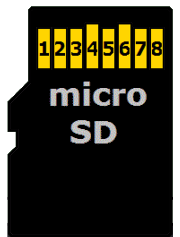
| microSD Card Pin | SPI Function |
|---|---|
| 1 | - |
| 2 | Chip Select (CS); also referred as Card Select |
| 3 | Data Input (DI) - corresponds to MOSI. To receive data from the microcontroller. |
| 4 | VDD - Power supply (3.3 V) |
| 5 | Serial Clock (SCK) |
| 6 | Ground (GND) |
| 7 | Data Output (DO) - corresponds to MISO. To send data from the microSD card to the microcontroller. |
| 8 | - |
Connecting the Raspberry Pi Pico to the SD Card Reader
The Raspberry Pi Pico’s GPIO pins are 3.3 V tolerant and can be permanently damaged by 5 V signals. Micro SD cards also operate at 3.3 V and can be damaged if higher voltages are applied.
SD card reader modules come in different configurations:
3.3 V-only modules: These modules are simple microSD breakout boards designed to run directly at 3.3 V. Because both the Raspberry Pi Pico and the SD card use the same voltage, the module can be connected without any extra circuitry. Power it from the Pico’s 3V3(OUT) pin and connect the SPI data lines directly to the Pico’s GPIO pins. This is the simplest and safest option when working with the Raspberry Pi Pico.
5 V modules with voltage regulation: Some SD card modules are designed to be powered from 5 V. These modules include extra components so the SD card itself still runs at 3.3 V. Some higher-quality modules also make sure that all signal lines stay at safe 3.3 V levels.
If a 5 V module is designed correctly, it can be used with the Raspberry Pi Pico. However, not all 5 V modules handle the signal levels properly. Because of this, you should always check the module description or documentation before connecting it to the Pico.
The Module Used in This Guide
The SD card module used in this guide is designed to be powered from 5 V and outputs 3.3 V signals, making it safe to use with the Raspberry Pi Pico.
Power the module from the Pico’s VBUS pin, which provides 5 V when the Pico is powered through USB. Do not power this type of module from the Pico’s 3.3 V pin, as it may not work reliably.
Caution
Always verify your SD card module outputs 3.3 V signals before connecting it to the Pico. If uncertain, use a 3.3 V-only module to avoid damaging your Pico.
Wiring Diagram
| Pico Pin | Wire | SD Card Pin |
|---|---|---|
| GPIO 4 (RX) |
|
MISO |
| GPIO 5 |
|
CS |
| GPIO 6 |
|
SCK |
| GPIO 7 (TX) |
|
MOSI |
| VBUS |
|
VCC |
| GND |
|
GND |
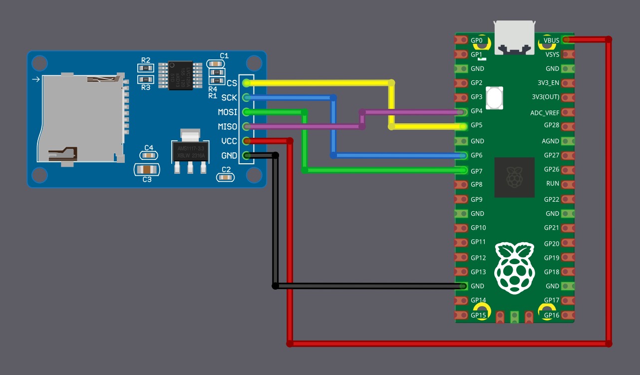
C 实现
Read SD Card with Raspberry Pi Pico
In this chapter, we are going to read a file from a microSD card and print its contents. Before continuing, you will need an SD card that is already formatted as FAT32, and it must contain a file named RUST.TXT. For this example, you can put the text Ferris inside.
Select Your Output Method
In this section, I have given two output methods. Which one you use depends on whether you have a debug probe or not.
There is no major difference in terms of logic or behavior. The program works the same way in both cases. The main difference is how the output is printed.
If you are using a debug probe, we print messages using defmt over RTT. If you are using USB serial, we print messages using the log crate.
The USB serial setup is the same as what we used in the earlier USB Serial chapter. You may need to follow the same steps to set up the USB logger. I will not be repeating those steps here.
From a code point of view, the difference mostly comes down to this:
- Since we use defmt with a debug probe, logging is done using defmt::info!
- On the other hand, when using USB serial, we use the log crate, so logging is done with log::info!.
Select the tab below based on your setup:
In this setup, we use defmt over RTT to print the file contents.
Project from template
We will start by creating a new project using the template.
cargo generate --git https://github.com/ImplFerris/pico2-template.git --tag v0.3.2
When prompted, enter a project name, for example “read-sdcard”, and select “Embassy” as the HAL. Ensure to enable “defmt” for logging.
Additional Crates required
Update your Cargo.toml to add these additional crate along with the existing dependencies.
# To convert Spi bus to SpiDevice
embedded-hal-bus = "0.3.0"
# sd card driver
embedded-sdmmc = "0.9.0"
The embedded-sdmmc crate is a driver for reading and writing files on FAT-formatted SD cards.
Additional imports
#![allow(unused)]
fn main() {
// For SPI
use embassy_rp::spi;
use embassy_rp::spi::Spi;
use embassy_time::Delay;
use embedded_hal_bus::spi::ExclusiveDevice;
// For CS Pin
use embassy_rp::gpio::{Level, Output};
// For SdCard
use embedded_sdmmc::{SdCard, TimeSource, Timestamp, VolumeIdx, VolumeManager};
}Dummy TimeSource
The SD card filesystem code requires a TimeSource implementation to supply timestamps for file metadata. Even though we are not creating or modifying files in this example, the trait still needs to be implemented.
Since timestamps are not important here, we use a dummy implementation that always returns zeroed values.
#![allow(unused)]
fn main() {
/// Code from https://github.com/rp-rs/rp-hal-boards/blob/main/boards/rp-pico/examples/pico_spi_sd_card.rs
/// A dummy timesource, which is mostly important for creating files.
#[derive(Default)]
pub struct DummyTimesource();
impl TimeSource for DummyTimesource {
// In theory you could use the RTC of the rp2040 here, if you had
// any external time synchronizing device.
fn get_timestamp(&self) -> Timestamp {
Timestamp {
year_since_1970: 0,
zero_indexed_month: 0,
zero_indexed_day: 0,
hours: 0,
minutes: 0,
seconds: 0,
}
}
}
}Setting up SPI for the SD card reader
Now we configure the SPI peripheral and the GPIO pins used to communicate with the SD card reader.
#![allow(unused)]
fn main() {
let miso = p.PIN_4;
let cs_pin = Output::new(p.PIN_5, Level::High);
let clk = p.PIN_6;
let mosi = p.PIN_7;
let mut config = spi::Config::default();
config.frequency = 400_000;
let spi_bus = Spi::new_blocking(p.SPI0, clk, mosi, miso, config);
}Creating an SpiDevice from the SPI bus
The SD card driver expects an SpiDevice, not a raw SPI bus.
#![allow(unused)]
fn main() {
let spi_device =
ExclusiveDevice::new(spi_bus, cs_pin, Delay).expect("Failed to get exclusive device");
}Setting up the SD card driver
With the SPI device ready, we can now create the SD card driver instance.
#![allow(unused)]
fn main() {
let sdcard = SdCard::new(spi_device, Delay);
}Reading the SD card size
Before opening any files, we read the total size of the card to confirm that initialization succeeded.
#![allow(unused)]
fn main() {
defmt::info!("Init SD card controller and retrieve card size...");
let sd_size = sdcard.num_bytes().expect("failed to get sdcard size");
defmt::info!("card size is {} bytes", sd_size);
}Opening the volume and root directory
Next, we create a volume manager and open the first volume on the card.
#![allow(unused)]
fn main() {
let volume_mgr = VolumeManager::new(sdcard, DummyTimesource::default());
let volume0 = volume_mgr
.open_volume(VolumeIdx(0))
.expect("failed to open volume");
let root_dir = volume0.open_root_dir().expect("failed to open root dir");
}Opening the file
With the root directory available, we open the file we want to read.
#![allow(unused)]
fn main() {
let my_file = root_dir
.open_file_in_dir("RUST.TXT", embedded_sdmmc::Mode::ReadOnly)
.expect("failed to open RUST.TXT file");
}Reading the file content
Finally, we read the file in small chunks and print its contents.
#![allow(unused)]
fn main() {
while !my_file.is_eof() {
let mut buffer = [0u8; 32];
if let Ok(n) = my_file.read(&mut buffer) {
if let Ok(s) = core::str::from_utf8(&buffer[..n]) {
defmt::info!("{}", s);
} else {
defmt::info!("{:02x}", &buffer[..n]);
}
}
}
}Clone the existing project
You can clone (or refer) project I created and navigate to the read-sdcard folder.
git clone https://github.com/ImplFerris/pico2-embassy-projects
cd pico2-embassy-projects/sdcard/read-sdcard/
Once the program is running, the output will show the contents of RUST.TXT file.
Write Data to an SD Card Using Embedded Rust on Raspberry Pi Pico
In this chapter, we create a file on a microSD card and write data into it. The SD card wiring, SPI configuration, logging setup, and card initialization remain unchanged. We only change how the file is opened and how data is written to it.
If the file already exists on the card, it will be overwritten. After the program runs, you can remove the card and verify the contents on your computer.
Project Setup
You can either reuse the project from the read example and modify it, or create a new project from the template and follow the same setup steps up to creating the sdcard instance.
From that point onward, only the file handling code is different.
Opening a file for writing
To write data, the file must be opened in a mode that allows creation and modification. Here we use ReadWriteCreateOrTruncate, which creates the file if it does not exist and truncates it if it already exists. This ensures that the file starts empty each time the program runs.
#![allow(unused)]
fn main() {
let my_file = root_dir
.open_file_in_dir(
"FERRIS.TXT",
embedded_sdmmc::Mode::ReadWriteCreateOrTruncate,
)
.expect("failed to create FERRIS.TXT file");
}Writing data to the file
To keep the example simple, we write a single line of text into the file. If the write succeeds, the file is flushed to ensure that the data is committed to the SD card.
#![allow(unused)]
fn main() {
let line = "Hello, Ferris!";
if let Ok(()) = my_file.write(line.as_bytes()) {
info!("Written Data");
if let Err(_) = my_file.flush() {
info!("Failed to flush");
}
} else {
error!("Unable to write the data");
}
}Clone the existing project
You can clone (or refer) project I created and navigate to the write-sdcard folder.
git clone https://github.com/ImplFerris/pico2-embassy-projects
cd pico2-embassy-projects/sdcard/write-sdcard/
Verifying the result
After the program finishes running, power off the board and remove the microSD card. When the card is inserted into a computer, a file named FERRIS.TXT should be present in the root directory.
Tip
In this example, we are using a dummy time source, so the file timestamp will appear around 1980. If you want correct timestamps, you will need to set up an RTC and provide a custom TimeSource implementation that returns the current time.
Opening the file should show:
Hello, Ferris!
Joystick
In this section, we’ll explore how to use the Joystick Module. It is similar to the joysticks found on PS2 (PlayStation 2) controllers. They are commonly used in gaming, as well as for controlling drones, remote-controlled cars, robots, and other devices to adjust position or direction.
Meet the hardware - Joystick module
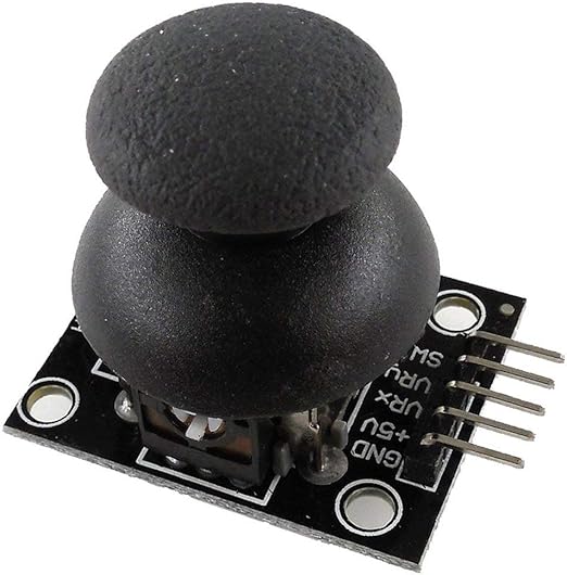
You can move the joystick knob vertically and horizontally, sending its position (X and Y axes) to the MCU (e.g., Pico). Additionally, the knob can be pressed down like a button. The joystick typically operates at 5 V, but it can also be connected to 3.3 V.
How it works?
The joystick module has two 10K potentiometers: one for the X-axis and another for the Y-axis. It also includes a push button, which is visible.
When you move the joystick from right to left or left to right (X axis), you can observe one of the potentiometers moving accordingly. Similarly, when you move it up and down (Y-axis), you can observe the other potentiometer moving along.
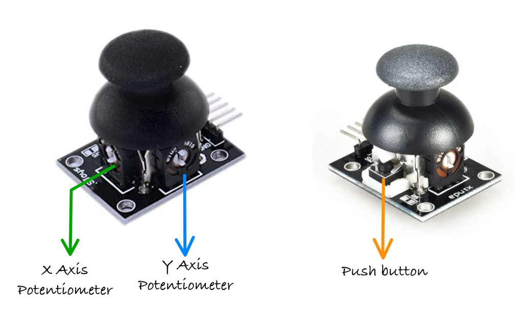
You can also observe the push-button being pressed when you press down on the knob.
方向与 ADC 值
Joystick Movement and Corresponding ADC Values
When you move the joystick along the X or Y axis, it produces an analog signal with a voltage that varies between 0 and 3.3 V (or 5 V if we connect it to 5 V supply). When the joystick is in its center (rest) position, the output voltage is approximately 1.65 V, which is half of the VCC (VCC is 3.3 V in our case).
Note
The reason it is 1.65 V in the center position is that the potentiometer acts as a voltage divider. When the potentiometer is moved, its resistance changes, causing the voltage divider to output a different voltage accordingly. Refer the voltate divider section.
The joystick has a total of 5 pins, and we will shortly discuss what each of them represents. Out of these, two pins are dedicated to sending the X and Y axis positions, which should be connected to the ADC pins of the microcontroller.
As you may already know, the Raspberry Pi Pico has a 12-bit SAR-type ADC, which converts analog signals (voltage differences) into digital values. Since it is a 12-bit ADC, the analog values will be represented as digital values ranging from 0 to 4095. If you’re not familiar with ADC, refer to the ADC section that we covered earlier.
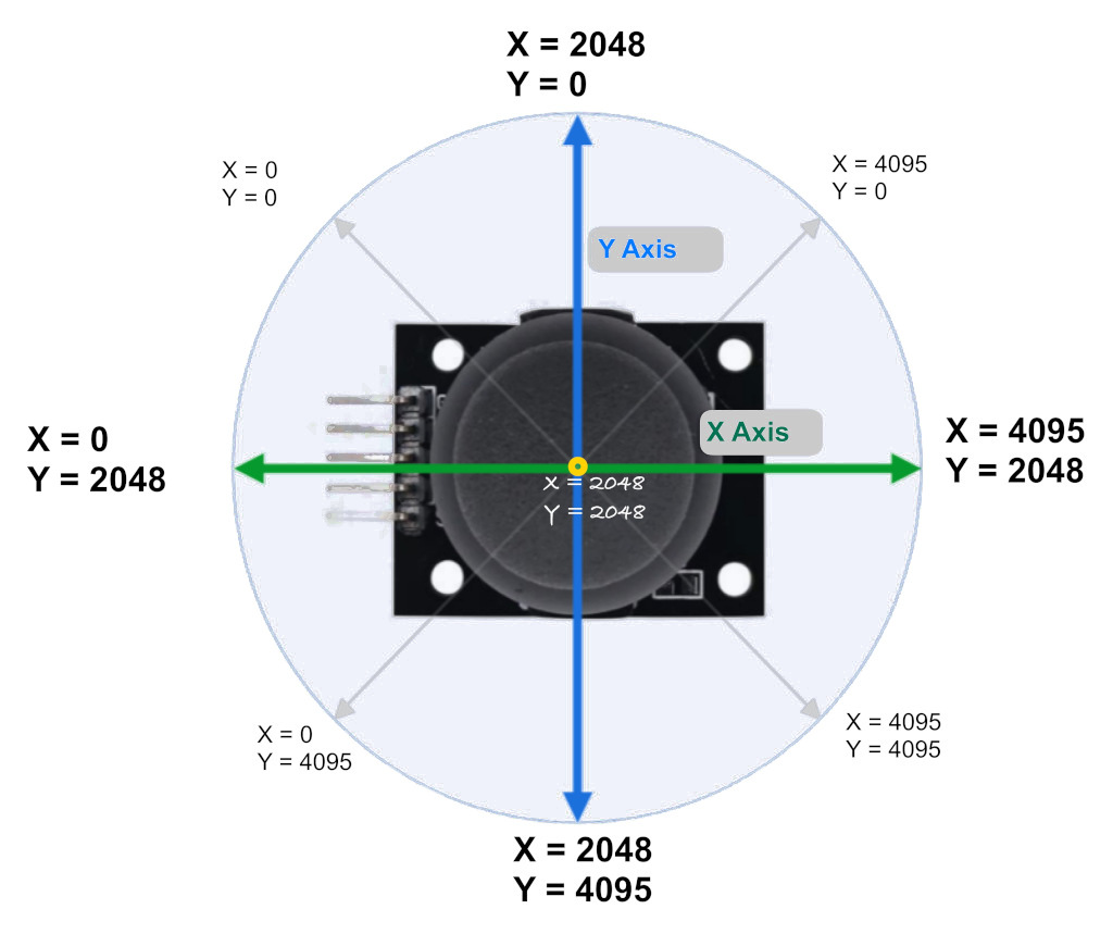
Note:
The ADC values in the image are just approximations to give you an idea and won’t be exact. For example, I got around 1850 for X and Y at the center position. When I moved the knob toward the pinout side, X went to 0, and when I moved it to the opposite side, it went to 4095. The same applies to the Y axis.So, You might need to calibrate your joystick.
Pin layout
The joystick has a total of 5 pins: power supply, ground, X-axis output, Y-axis output, and switch output pin.
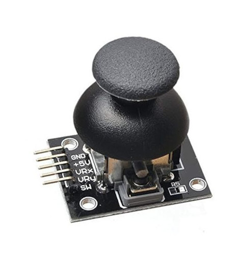
| Joystick Pin | Details |
|---|---|
| GND | Ground pin. Should be connected to the Ground of the circuit. |
| VCC | Power supply pin (typically 5 V or 3.3 V). |
| VRX | The X-axis analog output pin varies its voltage based on the joystick's horizontal position, ranging from 0 V to VCC as the joystick is moved left and right. |
| VRY | The Y-axis analog output pin varies its voltage based on the joystick's vertical position, ranging from 0 V to VCC as the joystick is moved up and down. |
| SW | Switch pin. When the joystick knob is pressed, this pin is typically pulled LOW (to GND). |
Connecting the Joystick to the Raspberry Pi Pico
Let’s connect the joystick to the Raspberry Pi Pico. We need to connect the VRX and VRY pins to the ADC pins of the Pico. The joystick will be powered with 3.3 V instead of 5 V because the Pico’s GPIO pins are only 3.3 V tolerant. Connecting it to 5 V could damage the Pico’s pins. Thankfully, the joystick can operate at 3.3 V as well.
| Pico Pin | Wire | Joystick Pin |
|---|---|---|
| GND |
|
GND |
| 3.3 V |
|
VCC |
| GPIO 27 (ADC1) |
|
VRX |
| GPIO 26 (ADC0) |
|
VRY |
| GPIO 15 |
|
SW |
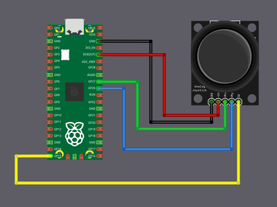
C 实现
Understanding Joystick Positions Using ADC Values on Raspberry Pi Pico
In this chapter, we are going to print the ADC values from the joystick whenever they change. We will read two analog signals, vrx and vry, which are connected to the joystick axes, and we will also print the values when the joystick button is pressed.
The goal here is simple. We want to see how the physical movement of the joystick translates into numeric ADC values. Once you see how the values change as you move it around, you can extend the idea and use it in projects such as controlling robots, RC vehicles, drones, pan-tilt camera mounts and more.
Project from template
We will start by generating a new project using the template.
cargo generate --git https://github.com/ImplFerris/pico2-template.git --tag v0.3.2
When prompted, give your project a name, for example joystick-adc, and select embassy as the HAL.
If you have a debug probe, you can enable defmt and logging will be straightforward. If you do not have a debug probe, disable defmt and use USB serial output, just like we did in the previous chapter. We will not repeat those steps here so that we can stay focused on the joystick and ADC setup.
Additional imports
Add the following imports to your main.rs file. These are needed for ADC access, GPIO input, and interrupt handling.
#![allow(unused)]
fn main() {
// For ADC
use embassy_rp::adc::{Adc, Channel, Config as AdcConfig};
use embassy_rp::gpio::{Input, Pull};
// Interrupt Binding
use embassy_rp::adc;
use embassy_rp::bind_interrupts;
}ADC Interrupt Binding
Next, we bind the ADC FIFO interrupt.
#![allow(unused)]
fn main() {
bind_interrupts!(struct Irqs {
ADC_IRQ_FIFO => adc::InterruptHandler;
});
}ADC and Joystick Setup
Now we initialize the ADC peripheral and set up the joystick pins. The vrx and vry signals are connected to GPIO pins that support ADC. And we also set up the joystick button as a regular input.
#![allow(unused)]
fn main() {
// ADC Setup
let mut adc = Adc::new(p.ADC, Irqs, AdcConfig::default());
let mut vrx_pin = Channel::new_pin(p.PIN_27, Pull::None);
let mut vry_pin = Channel::new_pin(p.PIN_26, Pull::None);
let button = Input::new(p.PIN_15, Pull::Up);
}Tracking Previous Values
Before we enter the main loop, we keep a few variables to track previous readings. This lets us detect when something actually changes instead of printing values continuously.
#![allow(unused)]
fn main() {
let mut prev_vrx: u16 = 0;
let mut prev_vry: u16 = 0;
let mut print_vals = true;
let mut prev_btn_state = false;
}We store the previous X and Y readings, keep a small flag to control when values should be printed, and also remember the previous button state so we can detect a button press event.
Main loop
Inside the main loop, we continuously read the ADC values from the two joystick pins. If an ADC read fails, we skip that iteration and try again.
#![allow(unused)]
fn main() {
loop {
let Ok(vry) = adc.read(&mut vry_pin).await else {
continue;
};
let Ok(vrx) = adc.read(&mut vrx_pin).await else {
continue;
};
}Detecting Meaningful Changes
Analog joysticks are not perfectly stable. Even when untouched, the readings can fluctuate slightly. To keep the output readable, we only react when the change is large enough to matter.
#![allow(unused)]
fn main() {
if vrx.abs_diff(prev_vrx) > 100 {
prev_vrx = vrx;
print_vals = true;
}
if vry.abs_diff(prev_vry) > 100 {
prev_vry = vry;
print_vals = true;
}
}When either axis changes beyond the threshold, we update the stored value and mark that the readings should be printed.
Printing ADC Values
If the print_vals flag is set, we print the current joystick position and then clear the flag.
#![allow(unused)]
fn main() {
if print_vals {
print_vals = false;
info!("X: {} Y: {}", vrx, vry);
}
}Handling the Button
Next, we read the joystick button. Because it uses a pull-up resistor, a pressed button reads as low.
#![allow(unused)]
fn main() {
let btn_state = button.is_low();
if btn_state && !prev_btn_state {
info!("Button Pressed");
print_vals = true;
}
prev_btn_state = btn_state;
}When the button is pressed, we mark the ADC values to be printed. This lets us see the exact joystick position at the moment of the press.
Finally, we add a short delay at the end of the loop.
#![allow(unused)]
fn main() {
Timer::after_millis(100).await;
}
}The full code
#![no_std]
#![no_main]
use defmt::info;
use embassy_executor::Spawner;
use embassy_rp as hal;
use embassy_rp::block::ImageDef;
use embassy_time::Timer;
// For ADC
use embassy_rp::adc::{Adc, Channel, Config as AdcConfig};
use embassy_rp::gpio::{Input, Pull};
// Interrupt Binding
use embassy_rp::adc;
use embassy_rp::bind_interrupts;
//Panic Handler
use panic_probe as _;
// Defmt Logging
use defmt_rtt as _;
/// Tell the Boot ROM about our application
#[unsafe(link_section = ".start_block")]
#[used]
pub static IMAGE_DEF: ImageDef = hal::block::ImageDef::secure_exe();
bind_interrupts!(struct Irqs {
ADC_IRQ_FIFO => adc::InterruptHandler;
});
#[embassy_executor::main]
async fn main(_spawner: Spawner) {
let p = embassy_rp::init(Default::default());
// ADC Setup
let mut adc = Adc::new(p.ADC, Irqs, AdcConfig::default());
let mut vrx_pin = Channel::new_pin(p.PIN_27, Pull::None);
let mut vry_pin = Channel::new_pin(p.PIN_26, Pull::None);
let button = Input::new(p.PIN_15, Pull::Up);
let mut prev_vrx: u16 = 0;
let mut prev_vry: u16 = 0;
let mut print_vals = true;
let mut prev_btn_state = false;
loop {
let Ok(vry) = adc.read(&mut vry_pin).await else {
continue;
};
let Ok(vrx) = adc.read(&mut vrx_pin).await else {
continue;
};
if vrx.abs_diff(prev_vrx) > 100 {
prev_vrx = vrx;
print_vals = true;
}
if vry.abs_diff(prev_vry) > 100 {
prev_vry = vry;
print_vals = true;
}
if print_vals {
print_vals = false;
info!("X: {} Y: {}", vrx, vry);
}
let btn_state = button.is_low();
if btn_state && !prev_btn_state {
info!("Button Pressed");
print_vals = true;
}
prev_btn_state = btn_state;
Timer::after_millis(100).await;
}
}
// Program metadata for `picotool info`.
// This isn't needed, but it's recommended to have these minimal entries.
#[unsafe(link_section = ".bi_entries")]
#[used]
pub static PICOTOOL_ENTRIES: [embassy_rp::binary_info::EntryAddr; 4] = [
embassy_rp::binary_info::rp_program_name!(c"joystick-adc"),
embassy_rp::binary_info::rp_program_description!(c"your program description"),
embassy_rp::binary_info::rp_cargo_version!(),
embassy_rp::binary_info::rp_program_build_attribute!(),
];
// End of fileClone the existing project
You can clone (or refer) project I created and navigate to the joystick-adc folder.
git clone https://github.com/ImplFerris/pico2-embassy-projects
cd pico2-embassy-projects/joystick/joystick-adc
Sending Joystick ADC Values to USB Serial (RP-HAL)
In the previous chapter, we used Embassy to read joystick ADC values and print them using logging. In the first version of this book, I was using RP-HAL while exploring and learning the ecosystem. I do not want to throw away that material, as it may still be useful for understanding older code or different approaches.
This chapter shows the same joystick ADC example implemented using RP-HAL and USB serial. If you are not interested in the RP-HAL version, you can skip this chapter.
Project from template
To set up the project, run:
cargo generate --git https://github.com/ImplFerris/pico2-template.git --tag v0.1.0
When prompted, give your project a name, like “joystick-usb” and select RP-HAL as the HAL.
Then, navigate into the project folder:
cd PROJECT_NAME
# For example, if you named your project "joystick-usb":
# cd joystick-usb
Additional Crates required
Update your Cargo.toml to add these additional crate along with the existing dependencies.
#![allow(unused)]
fn main() {
usb-device = "0.3.2"
usbd-serial = "0.2.2"
heapless = "0.8.0"
embedded_hal_0_2 = { package = "embedded-hal", version = "0.2.5", features = [
"unproven",
] }
}The first three should be familiar by now; they set up USB serial communication so we can send data between the Pico and the computer. heapless is a helper function for buffers.
embedded_hal_0_2 is the new crate. You might already have embedded-hal with version “1.0.0” in your Cargo.toml. So, you may wonder why we need this version. The reason is that Embedded HAL 1.0.0 doesn’t include an ADC trait to read ADC values, and the RP-HAL uses the one from version 0.2. (Don’t remove the existing embedded-hal 1.0.0; just add this one along with it.)
Additional imports
#![allow(unused)]
fn main() {
/// This trait is the interface to an ADC that is configured to read a specific channel at the time
/// of the request (in contrast to continuous asynchronous sampling).
use embedded_hal_0_2::adc::OneShot;
// for USB Serial
use usb_device::{class_prelude::*, prelude::*};
use usbd_serial::SerialPort;
use heapless::String;
}USB Serial
Make sure you’ve completed the USB serial section and added the boilerplate code from there into your project.
#![allow(unused)]
fn main() {
let usb_bus = UsbBusAllocator::new(hal::usb::UsbBus::new(
pac.USB,
pac.USB_DPRAM,
clocks.usb_clock,
true,
&mut pac.RESETS,
));
let mut serial = SerialPort::new(&usb_bus);
let mut usb_dev = UsbDeviceBuilder::new(&usb_bus, UsbVidPid(0x16c0, 0x27dd))
.strings(&[StringDescriptors::default()
.manufacturer("implRust")
.product("Ferris")
.serial_number("12345678")])
.unwrap()
.device_class(2) // 2 for the CDC, from: https://www.usb.org/defined-class-codes
.build();
let mut buff: String<64> = String::new();
}ADC and Pin Setup
The joystick wiring is the same as before. GPIO 27 and GPIO 26 are connected to the VRX and VRY pins of the joystick and are configured as ADC inputs. GPIO 15 is used for the joystick button with an internal pull-up.
#![allow(unused)]
fn main() {
let mut adc = hal::Adc::new(pac.ADC, &mut pac.RESETS);
//VRX Pin
let mut adc_pin_1 = hal::adc::AdcPin::new(pins.gpio27).unwrap();
// VRY pin
let mut adc_pin_0 = hal::adc::AdcPin::new(pins.gpio26).unwrap();
let mut btn = pins.gpio15.into_pull_up_input();
}Printing Co-ordinates
Just like in the Embassy version, we avoid printing ADC values continuously. We track the previous readings and only print when the change crosses a threshold. The same approach is used for the button. We detect a press by checking for a state transition, so the message is printed only once per press.
#![allow(unused)]
fn main() {
let mut prev_vrx: u16 = 0;
let mut prev_vry: u16 = 0;
let mut print_vals = true;
}Reading ADC Values:
First, read the ADC values for vrx and vry. If there’s an error during the read operation, we ignore it and continue the loop:
#![allow(unused)]
fn main() {
let Ok(vry): Result<u16, _> = adc.read(&mut adc_pin_0) else {
continue;
};
let Ok(vrx): Result<u16, _> = adc.read(&mut adc_pin_1) else {
continue;
};
}Checking for Threshold Changes:
Next, we check if the absolute difference between the current and previous values of vrx or vry exceeds a threshold (e.g., 100). If so, we update the previous values and set the print_vals flag to true:
#![allow(unused)]
fn main() {
if vrx.abs_diff(prev_vrx) > 100 {
prev_vrx = vrx;
print_vals = true;
}
if vry.abs_diff(prev_vry) > 100 {
prev_vry = vry;
print_vals = true;
}
}Using a threshold filters out small ADC fluctuations, avoids unnecessary prints, and ensures updates only for significant changes.
Printing the Coordinates
If print_vals is true, we reset it to false and print the X and Y coordinates via the USB serial:
#![allow(unused)]
fn main() {
if print_vals {
print_vals = false;
buff.clear();
write!(buff, "X: {} Y: {}\r\n", vrx, vry).unwrap();
let _ = serial.write(buff.as_bytes());
}
}Button Press Detection with State Transition
The button is normally in a high state. When you press the knob button, it switches from high to low. However, since the program runs in a loop, simply checking if the button is low could lead to multiple detections of the press. To avoid this, we only register the press once by detecting a high-to-low transition, which indicates that the button has been pressed.
To achieve this, we track the previous state of the button and compare it with the current state before printing the “button pressed” message. If the button is currently in a low state (pressed) and the previous state was high (not pressed), we recognize it as a new press and print the message. Then, we update the previous state to the current state, ensuring the correct detection of future transitions.
#![allow(unused)]
fn main() {
let btn_state = btn.is_low().unwrap();
if btn_state && !prev_btn_state {
let _ = serial.write("Button Pressed\r\n".as_bytes());
print_vals = true;
}
prev_btn_state = btn_state;
}The Full code
#![no_std]
#![no_main]
use core::fmt::Write;
use embedded_hal::{delay::DelayNs, digital::InputPin};
use embedded_hal_0_2::adc::OneShot;
use hal::block::ImageDef;
use heapless::String;
use panic_halt as _;
use rp235x_hal as hal;
use usb_device::{class_prelude::*, prelude::*};
use usbd_serial::SerialPort;
#[link_section = ".start_block"]
#[used]
pub static IMAGE_DEF: ImageDef = hal::block::ImageDef::secure_exe();
const XTAL_FREQ_HZ: u32 = 12_000_000u32;
#[hal::entry]
fn main() -> ! {
let mut pac = hal::pac::Peripherals::take().unwrap();
let mut watchdog = hal::Watchdog::new(pac.WATCHDOG);
let clocks = hal::clocks::init_clocks_and_plls(
XTAL_FREQ_HZ,
pac.XOSC,
pac.CLOCKS,
pac.PLL_SYS,
pac.PLL_USB,
&mut pac.RESETS,
&mut watchdog,
)
.ok()
.unwrap();
let mut timer = hal::Timer::new_timer0(pac.TIMER0, &mut pac.RESETS, &clocks);
let sio = hal::Sio::new(pac.SIO);
let pins = hal::gpio::Pins::new(
pac.IO_BANK0,
pac.PADS_BANK0,
sio.gpio_bank0,
&mut pac.RESETS,
);
// let mut led = pins.gpio25.into_push_pull_output();
let usb_bus = UsbBusAllocator::new(hal::usb::UsbBus::new(
pac.USB,
pac.USB_DPRAM,
clocks.usb_clock,
true,
&mut pac.RESETS,
));
let mut serial = SerialPort::new(&usb_bus);
let mut usb_dev = UsbDeviceBuilder::new(&usb_bus, UsbVidPid(0x16c0, 0x27dd))
.strings(&[StringDescriptors::default()
.manufacturer("implRust")
.product("Ferris")
.serial_number("12345678")])
.unwrap()
.device_class(2) // 2 for the CDC, from: https://www.usb.org/defined-class-codes
.build();
let mut btn = pins.gpio15.into_pull_up_input();
let mut adc = hal::Adc::new(pac.ADC, &mut pac.RESETS);
//VRX Pin
let mut adc_pin_1 = hal::adc::AdcPin::new(pins.gpio27).unwrap();
// VRY pin
let mut adc_pin_0 = hal::adc::AdcPin::new(pins.gpio26).unwrap();
let mut prev_vrx: u16 = 0;
let mut prev_vry: u16 = 0;
let mut prev_btn_state = false;
let mut buff: String<64> = String::new();
let mut print_vals = true;
loop {
let _ = usb_dev.poll(&mut [&mut serial]);
let Ok(vry): Result<u16, _> = adc.read(&mut adc_pin_0) else {
continue;
};
let Ok(vrx): Result<u16, _> = adc.read(&mut adc_pin_1) else {
continue;
};
if vrx.abs_diff(prev_vrx) > 100 {
prev_vrx = vrx;
print_vals = true;
}
if vry.abs_diff(prev_vry) > 100 {
prev_vry = vry;
print_vals = true;
}
let btn_state = btn.is_low().unwrap();
if btn_state && !prev_btn_state {
let _ = serial.write("Button Pressed\r\n".as_bytes());
print_vals = true;
}
prev_btn_state = btn_state;
if print_vals {
print_vals = false;
buff.clear();
write!(buff, "X: {} Y: {}\r\n", vrx, vry).unwrap();
let _ = serial.write(buff.as_bytes());
}
timer.delay_ms(50);
}
}
#[link_section = ".bi_entries"]
#[used]
pub static PICOTOOL_ENTRIES: [hal::binary_info::EntryAddr; 5] = [
hal::binary_info::rp_cargo_bin_name!(),
hal::binary_info::rp_cargo_version!(),
hal::binary_info::rp_program_description!(c"JoyStick USB"),
hal::binary_info::rp_cargo_homepage_url!(),
hal::binary_info::rp_program_build_attribute!(),
];Clone the existing project
You can clone (or refer) project I created and navigate to the joystick-usb folder.
git clone https://github.com/ImplFerris/pico2-rp-projects
cd pico2-projects/joystick-usb/
How to Run?
The method to flash (run the code) on the Pico is the same as usual. However, we need to set up tio to interact with the Pico through the serial port (/dev/ttyACM0). This allows us to read data from the Pico or send data to it.
tio
Make sure you have tio installed on your system. If not, you can install it using:
apt install tio
Connecting to the Serial Port
Run the following command to connect to the Pico’s serial port:
tio /dev/ttyACM0
This will open a terminal session for communicating with the Pico.
Flashing and Running the Code
Open another terminal, navigate to the project folder, and flash the code onto the Pico as usual:
cargo run
If everything is set up correctly, you should see a “Connected” message in the tio terminal. As you move the joystick, the coordinates will be printed. Pressing the knob downwards will also display a “Button pressed” message.
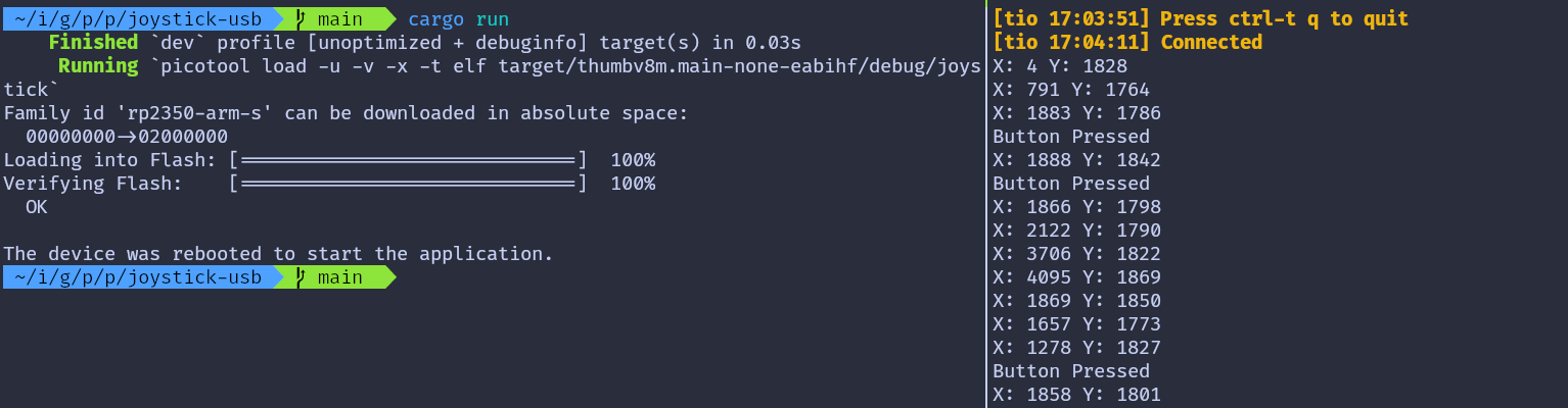
Debugging
C: GDB + OpenOCD
Debugging Embedded Rust on Raspberry Pi Pico 2 with GDB
In this chapter, we will look at how to debug Embedded Rust programs on the Raspberry Pi Pico 2 (RP2350) using GDB. You will need a Debug Probe hardware and you must connect it to your Raspberry Pi Pico 2. Make sure you have read chapter “Debug Probe for Raspberry Pi Pico 2” before continuing.
What a Debug Probe Gives You
In the Debug Probe introduction chapter, we saw that it helps you avoid pressing the BOOTSEL button every time you want to flash your program. But the Debug Probe offers much more than that. It allows you to use GDB directly from your computer, so you can debug your program while it is running on the Pico 2.
What is GDB?
If you have never used GDB, here is a simple explanation: GDB is a command line debugger that lets you pause your program, inspect what is happening inside it, read memory, and step through the code to find problems.
For debugging the Pico 2, you need a version of GDB that supports ARM targets. You can install it with:
sudo apt install gdb-multiarch
Enable GDB in Embed.toml
Earlier, we used probe-rs through the cargo embed command. The same tool can also start a GDB server, which lets you connect GDB to the Pico 2 through the Debug Probe.
For this, we need to edit the Embed.toml file in the root of your project. This file is the configuration file used by the cargo embed command. You should add the following section to enable the GDB server:
[default.gdb]
# Whether or not a GDB server should be opened after flashing.
enabled = true
Example Project
For this exercise, I have created a simple LED blink program using rp-hal. It does not use Embassy to keep things simple. The Embed.toml file is already set up, so you can clone the project and start working right away:
git clone https://github.com/ImplFerris/pico-debug
cd pico-debug
If you run the cargo embed command now, the GDB server will start automatically and listen on port 1337 (the default port used by probe-rs).
Connecting GDB to the Remote Server
To connect GDB to the running probe-rs GDB server, open a new terminal and start GDB with the our project binary file:
Note: There is an issue with probe-rs version 0.30. When I try to connect to the GDB server, the connection closes immediately. I downgraded to version 0.28 as suggested in this issue discussion. After downgrading, run cargo embed again.
gdb-multiarch ./target/thumbv8m.main-none-eabihf/debug/pico-debug
Then connect to the server on port 1337:
(gdb) target remote :1337
At this point, GDB is connected to the Pico 2 through the Debug Probe, and you can start using breakpoints, stepping, memory inspection, and other debugging commands.
Resetting to the Start of the Program
When you connect GDB to the running GDB server, the CPU may not be stopped at the start of your program. It might be sitting somewhere deep inside the code.
To ensure you start debugging from a clean state, run:
(gdb) monitor reset halt
This command tells the Debug Probe to reset the Pico 2 and immediately halt the CPU. This puts the program back at the very beginning, right where the processor starts running after a reset.
Finding the Reset Handler and Tracing the Call to main
When the Pico 2 resets, the CPU starts executing from the Reset Handler. To understand how our program starts, we will locate the Reset Handler, disassemble it, and follow the call chain until we reach our actual Rust main.
When the Pico 2 starts up, the CPU does not jump straight into our Rust main function. Instead, it follows a small chain of functions provided by the Cortex-M runtime.
In this section, we will:
-
Find where the chip starts executing after reset
-
See which function that Reset Handler calls
-
Follow the chain until we reach our real Rust main
Read the Reset Vector Entry
The Cortex-M processor starts execution by reading a table at the beginning of flash memory called the vector table.
The first two entries are:
- Word 0 (offset 0x00): Initial stack pointer value
- Word 1 (offset 0x04): Reset handler address
On Pico 2, flash starts at address 0x10000000 so:
- The initial stack pointer value is stored at 0x10000000
- Reset handler address is at 0x10000004
What is the Reset Handler?
The reset handler is the first function that runs when the processor powers on or resets. It performs initialization and eventually calls our main function.
Read it in GDB:
(gdb) x/wx 0x10000004
Example output - actual addresses might differ at your artifacts, use those to follow this chapters:
0x10000004 <__RESET_VECTOR>: 0x1000010d
This value is the address the CPU jumps to after reset. The last bit (the “Thumb bit”) is always 1, so the actual address is 0x1000010c.
But you can use either one of them (0x1000010d or 0x1000010c), GDB can handle it.
Alternatively, you can also use the readelf program to find the entrypoint address:
arm-none-eabi-readelf -h ./target/thumbv8m.main-none-eabihf/debug/pico-debug
Disassemble the Reset Handler
Now Let’s ask GDB to show the instructions at that address:
(gdb) disas 0x1000010d
# or
(gdb) disas 0x1000010c
You will see assembly instructions for the reset handler. Look for a bl (Branch with Link) instruction that calls another function:
...
0x10000140 <+52>: isb sy
0x10000144 <+56>: bl 0x1000031c <main>
0x10000148 <+60>: udf #0
The Reset Handler calls a function located at 0x1000031c, which GDB shows as main - but this is not our Rust main yet.
What is this “main”?
The main at 0x1000031c is not our program’s main function. It is a small wrapper created by the cortex-m-rt crate. This wrapper is often called the trampoline because it jumps to the real entry point later.
Its demangled name is usually:
#![allow(unused)]
fn main() {
// NOTE: here, pico_debug prefix is our project's name
pico_debug::__cortex_m_rt_main_trampoline
}Let’s disassemble it.
Disassemble that trampoline
(gdb) disas 0x1000031c
Output:
Dump of assembler code for function main:
0x1000031c <+0>: push {r7, lr}
0x1000031e <+2>: mov r7, sp
0x10000320 <+4>: bl 0x10000164 <_ZN10pico_debug18__cortex_m_rt_main17he0b4d19700c84ad2E>
End of assembler dump.
This is very small. All it does is call the real Rust entrypoint, which is named:
#![allow(unused)]
fn main() {
pico_debug::__cortex_m_rt_main
}Enable Demangled Names
Rust function names are mangled by default and look unreadable.
Enable demangling:
set print asm-demangle on
Now try:
(gdb) disas 0x1000031c
#or
(gdb) disas pico_debug::__cortex_m_rt_main_trampoline
You should now see readable Rust names.
Dump of assembler code for function pico_debug::__cortex_m_rt_main_trampoline:
0x1000031c <+0>: push {r7, lr}
0x1000031e <+2>: mov r7, sp
0x10000320 <+4>: bl 0x10000164 <pico_debug::__cortex_m_rt_main>
End of assembler dump.
Disassemble the Actual Rust main
Now let’s inspect our main function:
disas pico_debug::__cortex_m_rt_main
You will see the program’s logic, starting with the initial setup code followed by the loop that toggles the LED Pin.
#![allow(unused)]
fn main() {
...
0x100002dc <+376>: bl 0x100079a4 <rp235x_hal::timer::Timer<rp235x_hal::timer::CopyableTimer0>::new_timer0>
0x100002e0 <+380>: bl 0x10000b30 <rp235x_hal::gpio::Pin<rp235x_hal::gpio::pin::bank0::Gpio25, rp235x_hal::gpio::func::FunctionNull, rp235x_hal::gpio::pull::PullDown>::into_push_pull_output<rp235x_hal::gpio::pin::bank0::Gpio25, rp235x_hal::gpio::func::FunctionNull, rp235x_hal::gpio::pull::PullDown>>
...
0x100002f8 <+404>: bl 0x10000c48 <rp235x_hal::gpio::eh1::{impl#1}::set_high<rp235x_hal::gpio::pin::bank0::Gpio25, rp235x_hal::gpio::pull::PullDown>>
...
0x10000306 <+418>: bl 0x100006b8 <rp235x_hal::timer::{impl#7}::delay_ms<rp235x_hal::timer::CopyableTimer0>>
...
0x1000030c <+424>: bl 0x10000c38 <rp235x_hal::gpio::eh1::{impl#1}::set_low<rp235x_hal::gpio::pin::bank0::Gpio25, rp235x_hal::gpio::pull::PullDown>>
...
}Breakpoints
Now that we’ve traced the execution path from reset to our main function, let’s set breakpoints in the LED loop and observe how the GPIO registers change when we toggle the LED.
Understanding the LED Loop
Let me show you the disassembled code from the __cortex_m_rt_main function again. We need to look for the bl instructions. The bl stands for “branch and link” - these are instructions that call other functions. Specifically, we’re looking for the calls to set_high and set_low functions.
#![allow(unused)]
fn main() {
...
// This is the set_high() call
0x100002f8 <+404>: bl 0x10000c48 <rp235x_hal::gpio::eh1::{impl#1}::set_high<rp235x_hal::gpio::pin::bank0::Gpio25, rp235x_hal::gpio::pull::PullDown>>
...
// This is the delay_ms() call
0x10000306 <+418>: bl 0x100006b8 <rp235x_hal::timer::{impl#7}::delay_ms<rp235x_hal::timer::CopyableTimer0>>
...
// This is the set_low() call
0x1000030c <+424>: bl 0x10000c38 <rp235x_hal::gpio::eh1::{impl#1}::set_low<rp235x_hal::gpio::pin::bank0::Gpio25, rp235x_hal::gpio::pull::PullDown>>
...
// This is the delay_ms() call
0x10000314 <+432>: bl 0x100006b8 <rp235x_hal::timer::{impl#7}::delay_ms<rp235x_hal::timer::CopyableTimer0>>
...
}Look at those addresses on the left - 0x100002f8 and 0x1000030c. These are memory addresses where the LED control happens. The first address is where set_high gets called, and the second is where set_low gets called. We’re going to put breakpoints at these addresses so our program pauses right before running these instructions.
Setting Breakpoints in the Loop
Let’s set up the first breakpoint. Type this in GDB:
(gdb) break *0x100002f8
You’ll see: Breakpoint 1 at 0x100002f8: file src/main.rs, line 63.
This means GDB created a breakpoint at that address, and it corresponds to line 63 in our main.rs file.
(gdb) break *0x1000030c
You’ll see: Breakpoint 2 at 0x1000030c: file src/main.rs, line 65.
Now let’s reset everything to start fresh:
monitor reset halt
This resets the microcontroller and stops it at the beginning, so we have a clean starting point.
GPIO Register Overview
Before we continue, I need to explain what we’re going to look at. When you call set_high or set_low in your Rust code, what actually happens is that specific memory locations get changed. These memory locations are called registers, and they directly control the hardware.
On the RP2350 chip, there’s a register called GPIO_OUT that controls all the GPIO pins. You can find this in the RP2350 datasheet (chapter 3.1.11, page 55) under the SIO (Single-cycle IO) section.
Here’s where this register lives in memory:
- The SIO peripheral starts at base address
0xd0000000 - The GPIO_OUT register is at offset
0x010from that base - So the full address is:
0xd0000000+0x010=0xd0000010
Think of GPIO_OUT as a 32-bit number where each bit controls one GPIO pin. Bit 0 controls GPIO0, bit 1 controls GPIO1, and so on. Bit 25 controls GPIO25 - that’s where the onboard LED is connected. When bit 25 is 0, the LED is off. When bit 25 is 1, the LED is on.
Running to the First Breakpoint
Let’s run the program until it hits our first breakpoint:
(gdb) continue
When the breakpoint is hit, GDB will show something like:
Continuing.
Thread 1 hit Breakpoint 1, 0x100002f8 in pico_debug::__cortex_m_rt_main () at src/main.rs:63
63 led_pin.set_high().unwrap();
The program stopped right before calling set_high. This is the perfect moment to check what the register looks like before we turn the LED on.
Checking GPIO Registers Before set_high
Let’s look at what’s currently in the GPIO_OUT register:
(gdb) x/x 0xd0000010
The x/x command means “examine this memory address and show me the value in hexadecimal format.”
You’ll probably get an error message “Cannot access memory at address 0xd0000010”. This happens because GDB doesn’t automatically know about peripheral registers. We need to tell GDB that it’s allowed to read from this memory region.
Making SIO Peripheral Accessible in GDB
To fix this, we need to tell GDB about the peripheral memory region. According to the RP2350 datasheet, the SIO region actually extends from 0xd0000000 to 0xdfffffff. However, we don’t need to map the entire SIO region - we only need enough to cover the registers we want to access.
So we can type:
(gdb) mem 0xD0000000 0xD0001000 rw nocache
Here, we’re mapping about 4 KB of the SIO region (from 0xD0000000 to 0xD0001000), which is more than enough to cover GPIO_OUT and the other SIO registers we’ll be looking at during debugging.
If you want to map even less and be more precise, you can use:
(gdb) mem 0xD0000000 0xD0000100 rw nocache
This gives us just 256 bytes, which covers all the basic SIO registers we need, including GPIO_OUT at 0xD0000010. The key point is that we map enough memory to include the registers we want to read, without needing to map the entire SIO region.
Now try reading GPIO_OUT again:
(gdb) x/x 0xd0000010
0xd0000010: 0x00000000
We get the value 0x00000000. This means all 32 bits are zero, so all GPIO pins are currently off. Our LED is off.
Continue to the Second Breakpoint
Now let’s continue running and see what happens after set_high executes:
(gdb) continue
Continuing.
Thread 1 received signal SIGINT, Interrupt.
rp235x_hal::gpio::eh1::{impl#1}::set_high<rp235x_hal::gpio::pin::bank0::Gpio25, rp235x_hal::gpio::pull::PullDown> (self=0x2007ffbd)
at /home/implrust/.cargo/registry/src/index.crates.io-1949cf8c6b5b557f/rp235x-hal-0.3.1/src/gpio/mod.rs:1549
1549 fn set_high(&mut self) -> Result<(), Self::Error> {
We got interrupted inside the set_high function. Let’s continue again:
(gdb) continue
Continuing.
Thread 1 hit Breakpoint 2, pico_debug::__cortex_m_rt_main () at src/main.rs:65
65 led_pin.set_low().unwrap();
Now the program has run through set_high and the delay, and stopped at our second breakpoint on line 65, right before calling set_low. Let’s check GPIO_OUT again:
(gdb) x/x 0xd0000010
0xd0000010: 0x02000000
The value changed from 0x00000000 to 0x02000000. You should also see the LED turned on by this time.
Let me explain what 0x02000000 means. In binary, this is 00000010 00000000 00000000 00000000. If you count from the right starting at 0, bit 25 is now set to 1. That’s exactly what set_high did - it turned on bit 25 of the GPIO_OUT register, which turned on GPIO25, which lit up the LED.
Continue to See set_low in Action
Now let’s continue one more time to see what happens when set_low executes. But first, let’s note that the LED is currently on and GPIO_OUT shows 0x02000000 with bit 25 set to 1.
Let’s continue:
(gdb) continue
Continuing.
Thread 1 received signal SIGINT, Interrupt.
rp235x_hal::gpio::eh1::{impl#1}::set_low<rp235x_hal::gpio::pin::bank0::Gpio25, rp235x_hal::gpio::pull::PullDown> (self=0x2007ffbd)
at /home/implrust/.cargo/registry/src/index.crates.io-1949cf8c6b5b557f/rp235x-hal-0.3.1/src/gpio/mod.rs:1544
1544 fn set_low(&mut self) -> Result<(), Self::Error> {
We got interrupted inside the set_low function. Let’s continue again:
(gdb) continue
Continuing.
Thread 1 hit Breakpoint 1, 0x100002f8 in pico_debug::__cortex_m_rt_main () at src/main.rs:63
63 led_pin.set_high().unwrap();
The program ran through set_low and the delay, and looped back to our first breakpoint on line 63. Let’s check GPIO_OUT again:
(gdb) x/x 0xd0000010
0xd0000010: 0x00000000
The value is back to 0x00000000. Bit 25 is now 0, which means GPIO25 is off and the LED is off. You should see the LED turned off on your board.
What We Learned
From what we observed:
- When we call
led_pin.set_high(), bit 25 of GPIO_OUT changes from 0 to 1 (0x00000000→0x02000000) - When we call
led_pin.set_low(), bit 25 changes from 1 to 0 (0x02000000→0x00000000)
Atomic GPIO Register
Earlier, we looked only at the GPIO_OUT register. That register holds the full 32-bit output value for all GPIO pins. But in practice, the rp-hal library does not write to GPIO_OUT directly. Instead, it uses the atomic helper registers: GPIO_OUT_SET, GPIO_OUT_CLR, and GPIO_OUT_XOR.
These atomic registers are write-only registers within the SIO block that don’t hold values themselves. When you write to them, the bits you set are used to modify the underlying GPIO_OUT register:
- GPIO_OUT_SET changes specified bits to 1. This register is at address
0xd0000018, as per the datasheet. - GPIO_OUT_CLR changes specified bits to 0. This register is at address
0xd0000020, as per the datasheet. - GPIO_OUT_XOR toggles specified bits
Only the bits that we write as 1 are changed. All other bits stay untouched. This makes it safer and prevents accidental changes to other pins.
For example, if we want to control GPIO25:
-
To set GPIO25 high, we write a 1 to bit 25 of GPIO_OUT_SET. So the GPIO_OUT_SET value will be
0b00000010_00000000_00000000_00000000(or in hex0x02000000). -
To set GPIO25 low, we write a 1 to bit 25 of GPIO_OUT_CLR. So the GPIO_OUT_CLR value will be
0b00000010_00000000_00000000_00000000(or in hex0x02000000).
These operations modify only bit 25 in GPIO_OUT, leaving all other bits intact.
Inside rp-hal: Setting a Pin High or Low
If we follow what set_high() and set_low() do inside rp-hal, we can see that they never write to GPIO_OUT directly. Instead, they write to the atomic registers GPIO_OUT_SET and GPIO_OUT_CLR.
The code inside rp-hal looks like this:
#![allow(unused)]
fn main() {
#[inline]
pub(crate) fn _set_low(&mut self) {
let mask = self.id.mask();
self.id.sio_out_clr().write(|w| unsafe { w.bits(mask) });
}
#[inline]
pub(crate) fn _set_high(&mut self) {
let mask = self.id.mask();
self.id.sio_out_set().write(|w| unsafe { w.bits(mask) });
}
}When these write() functions run, they eventually call core::ptr::write_volatile(). write_volatile does some pre-checks, and then the compiler’s intrinsic intrinsics::volatile_store performs the final store to the MMIO address. That volatile store is the moment the actual hardware register changes.
Now let’s check how this looks when we step through it in GDB.
Breakpoint at write_volatile
There are many ways to reach write_volatile. One way is to step through set_low() or set_high() using stepi and nexti in GDB. But we will take a shorter path. We will set a breakpoint directly on core::ptr::write_volatile.
There is one thing to keep in mind. If you set this breakpoint right after reset (for example, right after monitor reset halt), GDB will stop many times. This is because write_volatile is used in a lot of places during startup. So we will not set it at the beginning.
Instead, follow the steps from the previous chapter. When the program stops at the first breakpoint in your code, like this:
Continuing.
Thread 1 hit Breakpoint 1, 0x100002f8 in pico_debug::__cortex_m_rt_main () at src/main.rs:63
63 led_pin.set_high().unwrap();
Tip
You can check your breakpoints with
info break. You can delete the breakpoint withdelete <number>.
Now that we’re past the startup code, let’s set our breakpoint on write_volatile:
(gdb) break core::ptr::write_volatile
Then continue execution:
(gdb) continue
You should see output similar to this:
Thread 1 received signal SIGINT, Interrupt.
rp235x_hal::gpio::eh1::{impl#1}::set_high<rp235x_hal::gpio::pin::bank0::Gpio25, rp235x_hal::gpio::pull::PullDown> (self=0x2007ffbd)
at /home/implrust/.cargo/registry/src/index.crates.io-1949cf8c6b5b557f/rp235x-hal-0.3.1/src/gpio/mod.rs:1549
1549 fn set_high(&mut self) -> Result<(), Self::Error> {
Continue again:
(gdb) continue
Now we’ve stopped inside the write_volatile function:
Thread 1 hit Breakpoint 3, core::ptr::write_volatile<u32> (dst=0xd0000018, src=33554432)
at /home/implrust/.rustup/toolchains/stable-x86_64-unknown-linux-gnu/lib/rustlib/src/rust/library/core/src/ub_checks.rs:76
76 if ::core::ub_checks::$kind() {
Did you notice the function arguments here? The destination dst is 0xd0000018, which is the address of the GPIO_OUT_SET register. The source value src is 33554432. If we convert that to hexadecimal, we get 0x02000000. In binary, that’s 0b00000010_00000000_00000000_00000000. This is the exact bit mask for GPIO25.
Let’s disassemble the function to see what’s happening at the assembly level:
(gdb) disas
Dump of assembler code for function _ZN4core3ptr14write_volatile17hc4948e781ca030f6E:
0x10008084 <+0>: push {r7, lr}
0x10008086 <+2>: mov r7, sp
0x10008088 <+4>: sub sp, #24
0x1000808a <+6>: str r2, [sp, #4]
0x1000808c <+8>: str r1, [sp, #8]
0x1000808e <+10>: str r0, [sp, #12]
0x10008090 <+12>: str r0, [sp, #16]
0x10008092 <+14>: str r1, [sp, #20]
=> 0x10008094 <+16>: b.n 0x10008096 <_ZN4core3ptr14write_volatile17hc4948e781ca030f6E+18>
0x10008096 <+18>: ldr r2, [sp, #4]
0x10008098 <+20>: ldr r0, [sp, #12]
0x1000809a <+22>: movs r1, #4
0x1000809c <+24>: bl 0x100080ac <_ZN4core3ptr14write_volatile18precondition_check17h8beabfccc7ba3236E>
0x100080a0 <+28>: b.n 0x100080a2 <_ZN4core3ptr14write_volatile17hc4948e781ca030f6E+30>
0x100080a2 <+30>: ldr r0, [sp, #8]
0x100080a4 <+32>: ldr r1, [sp, #12]
0x100080a6 <+34>: str r0, [r1, #0]
0x100080a8 <+36>: add sp, #24
0x100080aa <+38>: pop {r7, pc}
End of assembler dump.
The key instruction is at address 0x100080a6. This is the line that actually writes to the hardware register. At this point, r1 will contain the GPIO_OUT_SET address and r0 will contain the value that is going to be written.
Let’s take a closer look. We set another breakpoint right on that instruction:
(gdb) break *0x100080a6
Then continue:
(gdb) continue
If you get interrupted, continue again
Thread 1 received signal SIGINT, Interrupt.
core::ptr::write_volatile<u32> (dst=0xd0000018, src=33554432)
at /home/implrust/.rustup/toolchains/stable-x86_64-unknown-linux-gnu/lib/rustlib/src/rust/library/core/src/ub_checks.rs:77
77 precondition_check($($arg,)*);
Continue again:
(gdb) c
Continuing.
Thread 1 hit Breakpoint 4, 0x100080a6 in core::ptr::write_volatile<u32> (dst=0xd0000018, src=33554432)
at /home/implrust/.rustup/toolchains/stable-x86_64-unknown-linux-gnu/lib/rustlib/src/rust/library/core/src/ptr/mod.rs:2201
2201 intrinsics::volatile_store(dst, src);
GDB will stop exactly at the store instruction. If you run disas again, you’ll see the arrow pointing to that line:
...
0x100080a4 <+32>: ldr r1, [sp, #12]
=> 0x100080a6 <+34>: str r0, [r1, #0]
0x100080a8 <+36>: add sp, #24
Before we execute this write instruction, let’s check what values are in registers r0 and r1:
(gdb) i r $r0
r0 0x2000000 33554432
(gdb) i r $r1
r1 0xd0000018 3489660952
Let’s also examine the current value in the GPIO_OUT register:
(gdb) x/x 0xd0000010
0xd0000010: 0x00000000
Right now it shows all zeros. At this stage, the LED is still off because we haven’t executed the store instruction yet.
Now let’s step forward by one instruction:
(gdb) nexti
#or
(gdb) ni
After executing this command, you should see the LED turn on. Now let’s examine the GPIO_OUT register again:
(gdb) x/x 0xd0000010
0xd0000010: 0x02000000
The register now shows 0x02000000, which is exactly the bit mask for GPIO25. This confirms that our write operation successfully set the LED pin high.
Your Turn: Try It Yourself
Now it’s time to practice what you’ve learned. Let the program continue running until it hits the set_low breakpoint. Then continue execution again until you reach the write_volatile function.
This time, things will be a bit different. The destination address will be 0xd0000020, which is the GPIO_OUT_CLR register. As the name suggests, this register is used to clear GPIO pins rather than set them.
Step through the code just like before. When you execute the str instruction, the LED will turn off. If you examine the GPIO_OUT register afterwards, you’ll see it contains all zeros again. This confirms that the bit for GPIO25 has been cleared, turning off the LED.
Watchdog
This book was originally written using rp-hal. Later, I revised it to primarily use Embassy. When working with rp-hal, there is a step where we explicitly configure the watchdog. To explain why that line exists and what it actually does, this chapter introduces the concept of a watchdog.
In January 1994, the Clementine spacecraft successfully mapped the Moon. While it was traveling toward the asteroid Geographos, a floating point exception occurred on May 7, 1994, in the Honeywell 1750 processor. This processor handled telemetry and several other critical spacecraft functions.

The Honeywell 1750 included a built-in watchdog timer, but it was not used. After the failure, the software team publicly regretted this decision. They also noted that even a standard watchdog might not have been robust enough to detect that specific failure mode.
So what exactly is a watchdog, and why do we use it?
You may already have a rough idea.
What is watchdog?
A watchdog timer (WDT) is a hardware component commonly found in embedded systems. Its primary job is to detect software failures and automatically reset the processor when something goes wrong. This allows the system to recover without human intervention.
Watchdogs are especially important in systems that must run unattended for long periods of time.
How It Works?
A watchdog timer behaves like a countdown timer. It starts counting down from a configured value toward zero. The software must periodically reset this timer before it reaches zero.
This action is commonly called “feeding the watchdog”. You may also see it referred to as “kicking the dog”, although that term is widely used and I personally avoid it.
If the software fails to reset the timer in time, for example due to an infinite loop, a deadlock, or a system hang, the watchdog assumes the system is no longer healthy and triggers a processor reset. After the reset, the system can start again in a known good state.
Feeding the dog:
You can think of the watchdog timer like a dog that needs to be fed at regular intervals. As time passes, the dog gets hungrier. If it is not fed in time, it reacts. In embedded systems, that reaction is a hardware reset.
To keep the system running normally, the software must regularly feed the watchdog by resetting its counter.
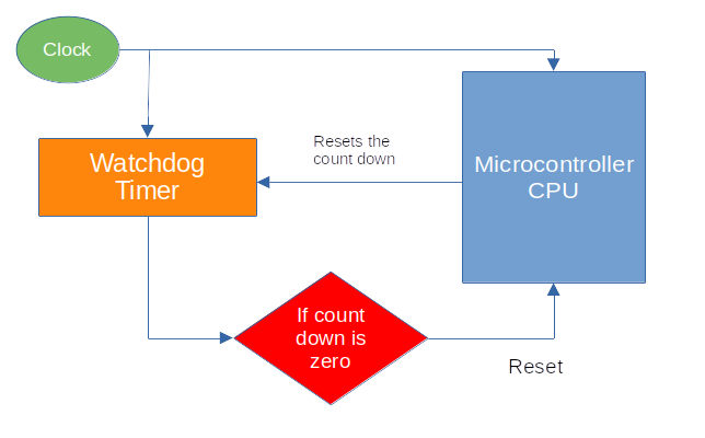
Code
In the following snippet, we set up the watchdog driver. This is required because the clock initialization code depends on the watchdog being available.
#![allow(unused)]
fn main() {
// Set up the watchdog driver - needed by the clock setup code
let mut watchdog = hal::Watchdog::new(pac.WATCHDOG);
}References
- Great Watchdog Timers For Embedded Systems, by Jack Ganssle
- Born to fail
- A Guide to Watchdog Timers for Embedded Systems
- Proper Watchdog Timer Use
C 实现
Curated List of Projects Written in Rust for Raspberry Pi Pico 2
Here is a curated list of projects I found online that are interesting and related to Pico 2 and Rust. If you have some interesting projects to showcase, please send a PR :)
- Pico Rex: Dinosaur Game written in Rust for the Raspberry Pi Pico 2 (RP2350) with an OLED display, using the Embassy framework.
- GB-RP2350 A Game Boy emulator for the Pi Pico 2 written in Rust: You can also find the reddit post by the OP.
- simple-robot: A very simple robot with HC-SR04 distance sensor and autonomous as well as remote controlled movement written in Rust (Embassy)
Useful resources
This section will include a list of resources I find helpful along the way.
Blog Posts
Tutorials
Other resources
- Curated list of resources for Embedded Rust
- Writing an OS in Rust: many useful concepts explained here
- Embassy Book